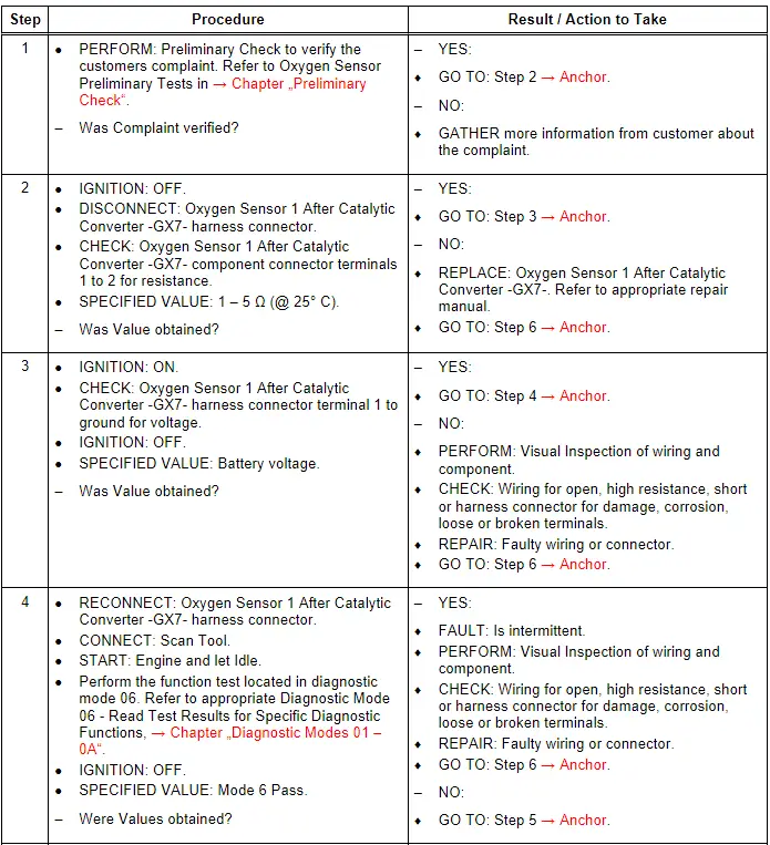
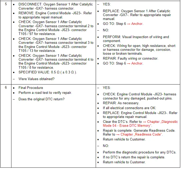
Audi Q7: Oxygen Sensor 1 After Catalytic Converter - GX7-, Checking
General Description
The Oxygen Sensor 1 After Catalytic Converter -GX7- is positioned downstream of the primary catalytic converter and it supplies the Engine Control Module -J623- with a voltage signal (nonlinear) indicating a "rich" or a "lean" condition is present. If the primary catalytic converter is supersaturated with oxygen (indicating a lean mixture is present), the Oxygen Sensor 1 After Catalytic Converter -GX7- will send the Engine Control Module -J623- a nonlinear signal indicating the lean mixture condition. The mixture is then enriched with fuel until the oxygen has been "displaced" from the catalytic converter. This new condition, in turn, is registered by the Oxygen Sensor 1 After Catalytic Converter -GX7- as a nonlinear signal indicating the rich mixture condition. The mixture is then leaned out by the Engine Control Module -J623-. If the nonlinear signal is received again, the mixture will again be enriched. The frequency, or period, during which the mixture is enriched or leaned out is variable, being dependent on the gas flow rate (engine load) at that moment.
Note the Oxygen Sensor 1 After Catalytic Converter -GX7- is also known as the Oxygen Sensor After Three Way Catalytic Converter -G130-.
The Oxygen Sensor 1 After Catalytic Converter -GX7- contains the following components:
- Oxygen Sensor After Three Way Catalytic Converter -G130-
- Heater For Oxygen Sensor 1 After Catalytic Converter -Z29-
The Oxygen Sensor 1 After Catalytic Converter -GX7- components cannot be serviced separately, and they must be serviced as a unit.
Special tools and workshop equipment required
- Multimeter.
- Wiring Diagram.
- Scan Tool.
Test requirements
- Fuses OK.
- Battery voltage OK.
- Switch OFF all electrical and electronic accessories.
- Vehicles with automatic transmission, ensure the selector lever position is in "P".
- Vehicles with manual transmission, ensure the shifter lever position is in "N" with the parking brake applied.
- Coolant temperature: ≥ 80º C.
- Observe all safety precautions: → Chapter "Safety Precautions".
- View clean working conditions: → Chapter "Clean Working Conditions".
- For Hybrid vehicles, refer to: → Chapter "High Voltage System General Warnings".
Test Procedure
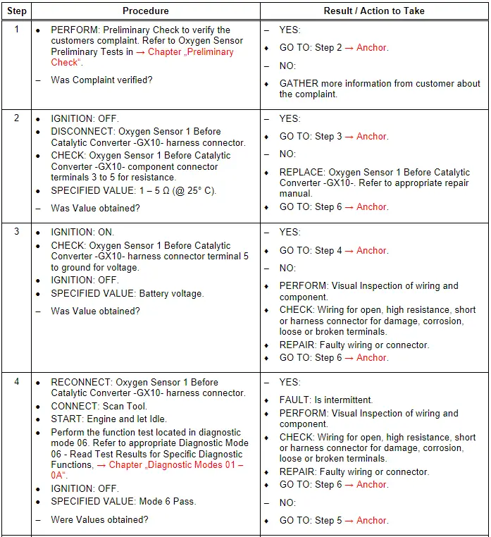
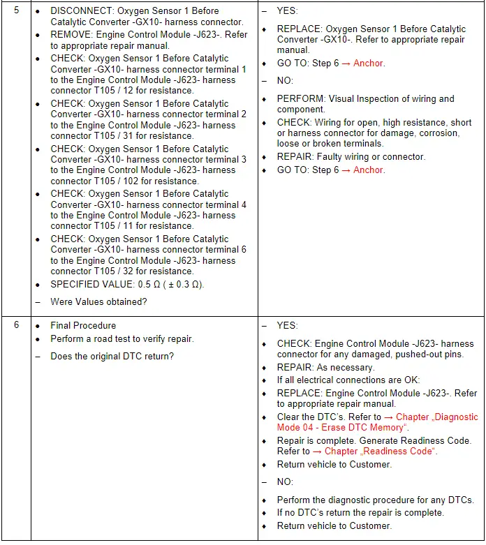
Oxygen Sensor 1 Before Catalytic Converter - GX10-, Checking
General Description
The Oxygen Sensor 1 Before Catalytic Converter -GX10- does not actually measure oxygen concentration, but rather the difference between the amount of oxygen in the exhaust gas and the amount of oxygen in the air. A rich mixture causes an oxygen demand. This demand causes a voltage to build up, due to transportation of oxygen ions through the Oxygen Sensor 1 Before Catalytic Converter -GX10- layer. A lean mixture causes a low voltage, since there is an oxygen excess. The Oxygen Sensor 1 Before Catalytic Converter -GX10- and catalytic converters are used in order to reduce exhaust emissions. Information on oxygen concentration is sent to the Engine Control Module -J623-, which adjusts the amount of fuel injected into the engine to compensate for excess air or excess fuel. The Engine Control Module -J623- attempts to maintain, on average, a certain air-fuel ratio by interpreting the information it gains from the Oxygen Sensor 1 Before Catalytic Converter -GX10-. The primary goal is a compromise between power, fuel economy, and emissions. The heater for the Oxygen Sensor 1 Before Catalytic Converter -GX10- is designed to minimize the time-to-readiness for closed-loop operation by heating the Oxygen Sensor 1 Before Catalytic Converter -GX10- as quickly as possible.
Note the Oxygen Sensor 1 Before Catalytic Converter -GX10- is also known as the Heated Oxygen Sensor -G39-.
The Oxygen Sensor 1 Before Catalytic Converter -GX10- contains the following components:
- Heated Oxygen Sensor -G39-
- Oxygen Sensor Heater -Z19-
The Oxygen Sensor 1 Before Catalytic Converter -GX10- components cannot be serviced separately, and they must be serviced as a unit.
Special tools and workshop equipment required
- Multimeter.
- Wiring Diagram.
- Scan Tool.
Test requirements
- Fuses OK.
- Battery voltage OK.
- Switch OFF all electrical and electronic accessories.
- Vehicles with automatic transmission, ensure the selector lever position is in "P".
- Vehicles with manual transmission, ensure the shifter lever position is in "N" with the parking brake applied.
- Coolant temperature: ≥ 80º C.
- Observe all safety precautions: → Chapter "Safety Precautions".
- View clean working conditions: → Chapter "Clean Working Conditions".
- For Hybrid vehicles, refer to: → Chapter "High Voltage System General Warnings".
Test Procedure
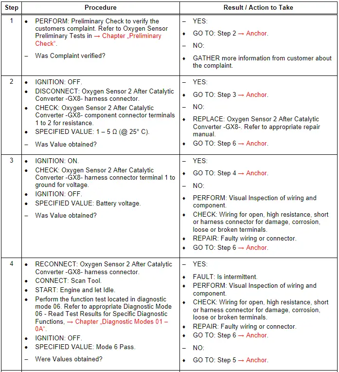
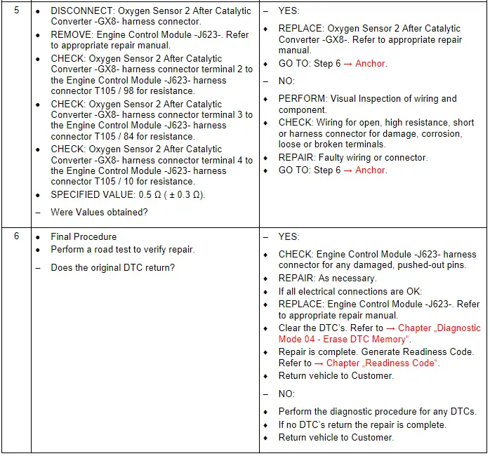
Oxygen Sensor 2 After Catalytic Converter - GX8-, Checking
General Description
The Oxygen Sensor 2 After Catalytic Converter -GX8- is positioned downstream of the primary catalytic converter and it supplies the Engine Control Module -J623- with a voltage signal (nonlinear) indicating a "rich" or a "lean" condition is present. If the primary catalytic converter is supersaturated with oxygen (indicating a lean mixture is present), the Oxygen Sensor 2 After Catalytic Converter -GX8- will send the Engine Control Module -J623- a nonlinear signal indicating the lean mixture condition. The mixture is then enriched with fuel until the oxygen has been "displaced" from the catalytic converter. This new condition, in turn, is registered by the Oxygen Sensor 2 After Catalytic Converter -GX8- as a nonlinear signal indicating the rich mixture condition. The mixture is then leaned out by the Engine Control Module -J623-. If the nonlinear signal is received again, the mixture will again be enriched. The frequency, or period, during which the mixture is enriched or leaned out is variable, being dependent on the gas flow rate (engine load) at that moment.
Note the Oxygen Sensor 2 After Catalytic Converter -GX8- is also known as the Oxygen Sensor 2 After Catalytic Converter -G131-.
The Oxygen Sensor 2 After Catalytic Converter -GX8- contains the following components:
- Oxygen Sensor 2 After Catalytic Converter -G131-
- Heater For Oxygen Sensor 2 After Catalytic Converter -Z30-
The Oxygen Sensor 2 After Catalytic Converter -GX8- components cannot be serviced separately, and they must be serviced as a unit.
Special tools and workshop equipment required
- Multimeter.
- Wiring Diagram.
- Scan Tool.
Test requirements
- Fuses OK.
- Battery voltage OK.
- Switch OFF all electrical and electronic accessories.
- Vehicles with automatic transmission, ensure the selector lever position is in "P".
- Vehicles with manual transmission, ensure the shifter lever position is in "N" with the parking brake applied.
- Coolant temperature: ≥ 80º C.
- Observe all safety precautions: → Chapter "Safety Precautions".
- View clean working conditions: → Chapter "Clean Working Conditions".
- For Hybrid vehicles, refer to: → Chapter "High Voltage System General Warnings".
Test Procedure
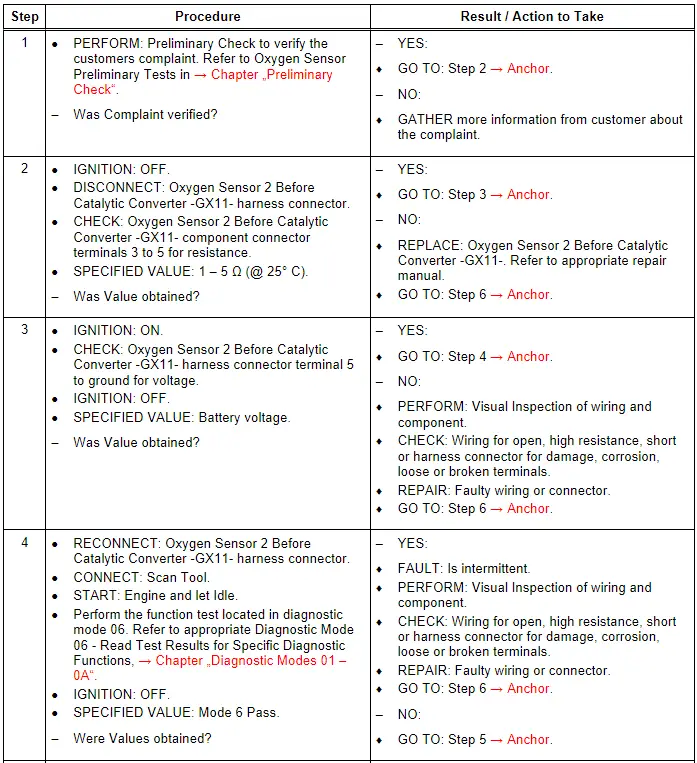
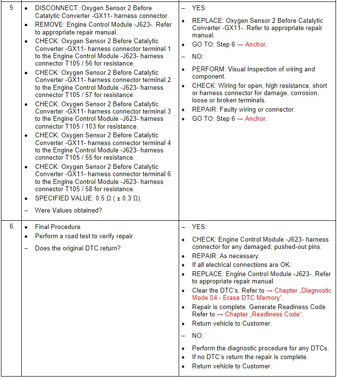
Oxygen Sensor 2 Before Catalytic Converter - GX11-, Checking
General Description
The Oxygen Sensor 2 Before Catalytic Converter -GX11- does not actually measure oxygen concentration, but rather the difference between the amount of oxygen in the exhaust gas and the amount of oxygen in the air. A rich mixture causes an oxygen demand. This demand causes a voltage to build up, due to transportation of oxygen ions through the Oxygen Sensor 2 Before Catalytic Converter -GX11- layer. A lean mixture causes a low voltage, since there is an oxygen excess. The Oxygen Sensor 2 Before Catalytic Converter -GX11- and catalytic converters are used in order to reduce exhaust emissions. Information on oxygen concentration is sent to the Engine Control Module -J623-, which adjusts the amount of fuel injected into the engine to compensate for excess air or excess fuel. The Engine Control Module -J623- attempts to maintain, on average, a certain air-fuel ratio by interpreting the information it gains from the Oxygen Sensor 2 Before Catalytic Converter -GX11-. The primary goal is a compromise between power, fuel economy, and emissions. The heater for the Oxygen Sensor 2 Before Catalytic Converter -GX11- is designed to minimize the time-to-readiness for closed-loop operation by heating the Oxygen Sensor 2 Before Catalytic Converter -GX11- as quickly as possible.
Note the Oxygen Sensor 2 Before Catalytic Converter -GX11- is also known as the Heated Oxygen Sensor 2 -G108-.
The Oxygen Sensor 2 Before Catalytic Converter -GX11- contains the following components:
- Heated Oxygen Sensor 2 -G108-
- Oxygen Sensor 2 Heater -Z28-
The Oxygen Sensor 2 Before Catalytic Converter -GX11- components cannot be serviced separately, and they must be serviced as a unit.
Special tools and workshop equipment required
- Multimeter.
- Wiring Diagram.
- Scan Tool.
Test requirements
- Fuses OK.
- Battery voltage OK.
- Switch OFF all electrical and electronic accessories.
- Vehicles with automatic transmission, ensure the selector lever position is in "P".
- Vehicles with manual transmission, ensure the shifter lever position is in "N" with the parking brake applied.
- Coolant temperature: ≥ 80º C.
- Observe all safety precautions: → Chapter "Safety Precautions".
- View clean working conditions: → Chapter "Clean Working Conditions".
- For Hybrid vehicles, refer to: → Chapter "High Voltage System General Warnings".
Test Procedure