Audi Q7: Secondary Air System
Overview - Secondary Air Injection System
Secondary Air Injection Pump Motor -V101-
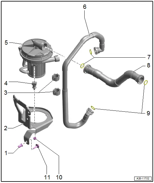
1 - Pop Rivet Nut
- Drill out to replace
2 - Bracket
- For the Secondary Air Injection Pump Motor -V101-
3 - Clips
4 - Bonded Rubber Bushing
5 - Secondary Air Injection Pump Motor -V101-
- Installed location: in the front of the engine compartment on the left side under the longitudinal member
- Checking using Vehicle Diagnostic Tester.
- Removing and installing. Refer to → Chapter "Secondary Air Injection Pump Motor -V101-, Removing and Installing".
6 - Pipe
- For secondary air injection
7 - O-Rings
- Replace after removing
8 - Pipe
- For secondary air injection
9 - O-Rings
- Replace after removing
10 - Nut
- 9 Nm
11 - Bolt
- 20 Nm
Secondary Air Injection Combination Valve
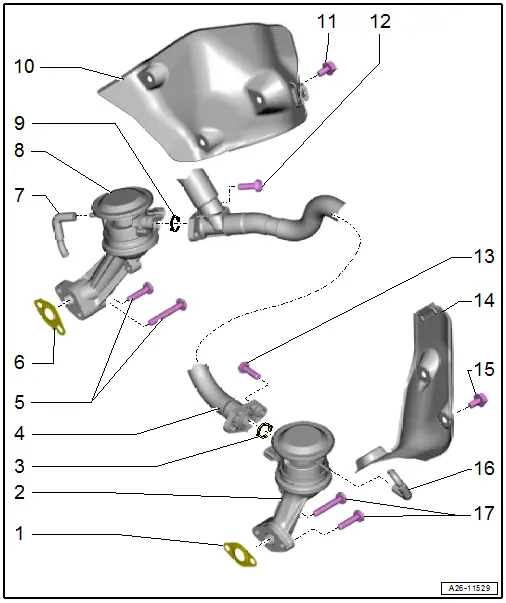
1 - Seal
- Replace after removing
2 - Left Secondary Air Injection Combination Valve
- Check the functionality and for leaks. Refer to → Chapter "Secondary Air Injection Solenoid Valve, Checking"
- Removing and installing. Refer to → Chapter "Left Combination Valve, Removing and Installing".
3 - Seal
- Replace after removing
4 - Hose
- From the Secondary Air Injection Pump Motor -V101-
5 - Bolts
- 9 Nm
6 - Seal
- Replace after removing
7 - Vacuum Hose
8 - Right Secondary Air Injection Combination Valve
- Check the functionality and for leaks. Refer to → Chapter "Secondary Air Injection Solenoid Valve, Checking"
- Removing and installing. Refer to → Chapter "Right Combination Valve, Removing and Installing".
9 - Seal
- Replace after removing
10 - Heat Shield
11 - Bolt
- 9 Nm
12 - Bolt
- 9 Nm
13 - Bolt
- 9 Nm
14 - Heat Shield
15 - Bolt
- 9 Nm
16 - Vacuum Hose
17 - Bolts
- 9 Nm
Secondary Air Injection Pump Motor -V101-, Removing and Installing
 Caution
This procedure contains mandatory replaceable parts. Refer to component overview prior to starting procedure.
Mandatory Replacement Parts
- O-rings - Hoses for secondary air injection pump motor
Removing
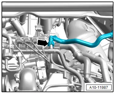
- Disconnect the connector -2- on the Secondary Air Injection Pump Motor -V101-.
- Press the release buttons on both sides and remove the secondary air injection hoses -1-.
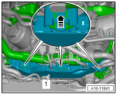
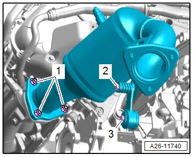
- Remove the bolts -arrows- and the Secondary Air Injection Pump Motor -V101-.
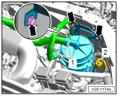
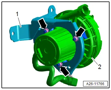
- Remove the nuts -arrows- and remove the Secondary Air Injection Pump Motor -V101--2- from the bracket -1-.
Installing
Install in reverse order of removal and note the following:
 Note
Note
Replace the O-rings after removing them.
Tightening Specifications
- Refer to → Chapter "Overview - Secondary Air Injection System"
Secondary Air Injection Solenoid Valve, Checking
Special tools and workshop equipment required
- Hand Vacuum Pump -VAS6213-
 Caution
This procedure contains mandatory replaceable parts. Refer to component overview prior to starting procedure.
Mandatory Replacement Parts
- O-ring - Secondary air injection hose
Procedure
- Vacuum lines and hose connections free of leaks.
- Vacuum lines not blocked.
- Remove the Throttle Valve Control Module -J338-. Refer to → Chapter "Throttle Valve Control Module -J338-, Removing and Installing".
- Disconnect the vacuum connection -arrow- by pressing the release buttons on both sides.

- Disconnect the connectors -1 to 4- and free up the wires.
 Note
Note
Ignore -5-.
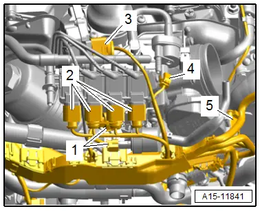
- Release the catches in direction of -arrow- and push the wiring duct -1- slightly to the rear.
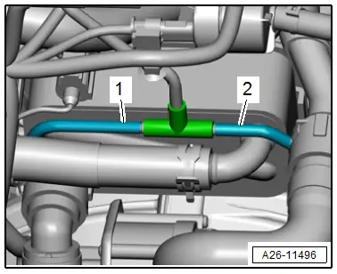
- Remove the vacuum hose -1 or 2- on the combination valve being checked.
- Connect the Hand Vacuum Pump - VAS6213- to the vacuum hose for the combination valve to be checked.
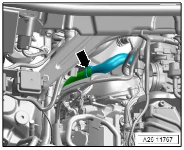
- Press the release buttons to remove the secondary air injection hose -arrow- from the Secondary Air Injection Pump Motor -V101-.
- Extend the secondary air injection hose with an adapter hose and blow lightly into the adapter hose by mouth, do not use compressed air.
- The secondary air injection combination valves must be closed. It must not be possible to blow through.
- Operate the hand vacuum pump.
- The relevant combination valve must open, it must be possible to blow through
- If the secondary air combination valve does not open, replace it. Refer to → Chapter "Combination Valve, Removing and Installing".
Assembling
Assemble in the reverse order of removal. Note the following:
 Note
Note
Replace the O-ring after removing.
- Connections and wire routing. Refer to → Wiring diagrams, Troubleshooting & Component locations.
- Install the Throttle Valve Control Module -J338-. Refer to → Chapter "Throttle Valve Control Module -J338-, Removing and Installing".
Combination Valve, Removing and Installing
Left Combination Valve, Removing and Installing
 Caution
This procedure contains mandatory replaceable parts. Refer to component overview prior to starting procedure.
Mandatory Replacement Parts
- Lock Nuts - Front muffler
- Seals - Catalytic Converter
- Seal - Combination Valve
Removing
 Note
Note
During installation, all cable ties must be installed at the same location.
- Remove the air filter housing. Refer to → Chapter "Air Filter Housing, Removing and Installing".
- Disconnect the brake booster vacuum hose -arrow- by pressing the release buttons on both sides.
- Remove the left front muffler. Refer to → Chapter "Front Muffler, Removing and Installing".
- Free up the Oxygen Sensor 2 after Catalytic Converter -G131- wire.
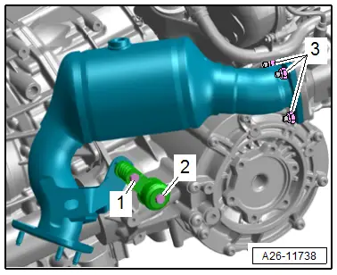
- Remove the bolts -2 and 3- and remove the mounting.
- Remove the nuts -1- and disconnect the left catalytic converter from the exhaust manifold and push it rearward.
- Free up the wiring harness and push it to the side.
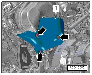
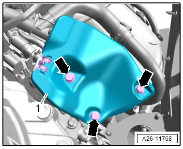
- Remove the bolts -arrows- and remove the heat shield -1-.
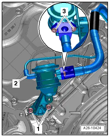
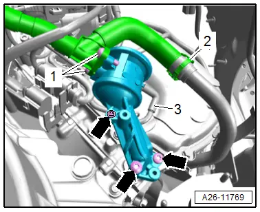
- Remove the vacuum line -2- from the secondary air injection combination valve.
- Remove the bolts -1- and remove the secondary air injection combination valve.
- Remove the bolts -3- for the secondary air injection hose.
Installing
Install in reverse order of removal and note the following:
 Note
Note
Replace the seal after removal.
- Connections and wire routing. Refer to → Wiring diagrams, Troubleshooting & Component locations.
- Install the left catalytic converter. Refer to → Chapter "Left Catalytic Converter, Removing and Installing".
- Install the air filter housing. Refer to → Chapter "Air Filter Housing, Removing and Installing".
Tightening Specifications
- Refer to → Chapter "Overview - Secondary Air Injection System"
Right Combination Valve, Removing and Installing
 Caution
This procedure contains mandatory replaceable parts. Refer to component overview prior to starting procedure.
Mandatory Replacement Parts
- Lock Nuts - Front muffler
- Seals - Catalytic Converter
- Seal - Combination Valve
Removing
 Note
Note
During installation, all cable ties must be installed at the same location.
- Remove the Throttle Valve Control Module -J338-. Refer to → Chapter "Throttle Valve Control Module -J338-, Removing and Installing".
- Remove the right front muffler. Refer to → Chapter "Front Muffler, Removing and Installing".
- Remove the right subframe shield. Refer to → Suspension, Wheels, Steering; Rep. Gr.40; Subframe; Subframe Shield, Removing and Installing.
- Free up the Oxygen Sensor 2 after Catalytic Converter -G131- wire.
- Remove the bolts -1 and 2- and the mounting.
- Remove the nuts -3-.
- Remove the right catalytic converter from the exhaust manifold and move toward the rear.
- Remove the bolts -arrows- and remove the heat shield -1-.
- Remove the vacuum line -3- from the secondary air injection combination valve.
- Remove the secondary air injection hose -2- by pressing both the release buttons.
- Remove the bolts -arrows-, remove the right secondary air injection combination valve and remove the screws -1- for the secondary air injection hose.
Installing
Install in reverse order of removal and note the following:
 Note
Note
Replace the seal after removal.
- Connections and wire routing. Refer to → Wiring diagrams, Troubleshooting & Component locations.
- Install the right catalytic converter. Refer to → Chapter "Right Catalytic Converter, Removing and Installing".
- Install the Throttle Valve Control Module -J338-. Refer to → Chapter "Throttle Valve Control Module -J338-, Removing and Installing".
Tightening Specifications
- Refer to → Chapter "Overview - Secondary Air Injection System"
- Refer to → Suspension, Wheels, Steering; Rep. Gr.40; Subframe; Overview - Subframe.

