Audi Q7: High Pressure Pump
Overview - High Pressure Pump
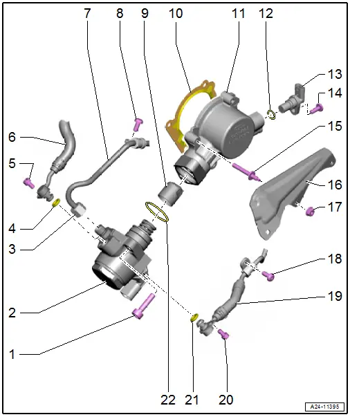
1 - Bolt
- Tightening specification and sequence. Refer to → Fig. "High Pressure Pump - Tightening Specification and Sequence".
2 - High Pressure Pump
- With Fuel Metering Valve -N290-
- Do not disassemble
- Removing and installing. Refer to → Chapter "High Pressure Pump, Removing and Installing".
3 - Union Nut
- 27 Nm
- Coat the threads on the union nut with fuel.
4 - O-Ring
- Replace after removing
5 - Bolt
- 9 Nm
6 - Fuel Supply Hose with Connection
- Low pressure side from the fuel tank
7 - High Pressure Line
- Removing and installing. Refer to → Chapter "High Pressure Pipe, Removing and Installing".
- Do not change the bending shape.
- Check for damage before reinstalling
8 - Bolt
- 9 Nm
9 - Roller Tappet
- Can only be installed in one position
- Coat with clean engine oil before installing
10 - Seal
- Replace after removing
11 - Housing
12 - O-Ring
- Replace after removing
13 - Camshaft Position Sensor -G40-
- Removing and installing. Refer to → Chapter "Camshaft Position Sensor, Removing and Installing".
14 - Bolt
- Tightening specification. Refer to -item 14-
15 - Threaded Pin
- 9 Nm
16 - Protective Plate
- For the high pressure line
17 - Nut
- 9 Nm
18 - Bolt
- 9 Nm
19 - Fuel Supply Hose with Connection
- Low pressure side to the MPI fuel injector
20 - Bolt
- 9 Nm
21 - O-Ring
- Replace after removing
22 - O-Ring
- Replace after removing
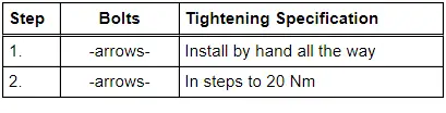
High Pressure Pump - Tightening Specification and Sequence
- Tighten the bolts in stages as follows:
High Pressure Pump, Removing and Installing
Special tools and workshop equipment required
- Torque Wrench 1331 Insert - Reversible Ratchet -VAG1331/1-
- Torque Wrench 1331 Insert - Open Ring Wrench - 14mm -VAG1331/8-
- Engine Bung Set -VAS6122-
- Elbow Assembly Tool -T10118-
- Crankshaft Socket -T40058-
- Feeler Gauge
 Caution
This procedure contains mandatory replaceable parts. Refer to component overview prior to starting procedure.
Mandatory Replacement Parts
- O-ring - High pressure pump
- O-ring - Fuel supply hose with connection
Removing
 Note
Note
- The high pressure pump can only be removed and installed when the engine is cold.
- When installing the high pressure pump, make sure that no dirt enters the fuel system.
- Catch escaping fuel with a cleaning cloth.
- Remove the engine cover. Refer to → Chapter "Engine Cover, Removing and Installing".
- Remove the lock carrier cover. Refer to → Body Exterior; Rep. Gr.63; Front Bumper; Attachments, Removing and Installing.
- Remove the Secondary Air Injection Pump Motor -V101-. Refer to → Chapter "Secondary Air Injection Pump Motor -V101-, Removing and Installing".
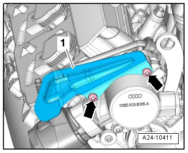
- Remove the nuts -arrows- and the protective plate -1-.
 WARNING
The fuel system is under pressure.
Risk of injury from fuel spraying out.
- Wear protective eyewear.
- Wear safety gloves.
- Reduce the pressure: place clean cloths around the connection point and carefully open the connection point.
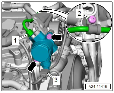
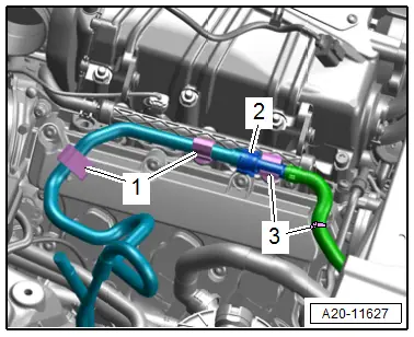
- Disconnect the fuel hose -2-. Refer to → Fuel Supply - Gasoline Engines; Rep. Gr.20; Connector Couplings; Connector Couplings, Disconnecting.
- Always seal the open lines and connections with clean plugs from the Engine Bung Set -VAS6122-.
- Free up the fuel hose from the clips -3-.
 Note
Note
Ignore -1-.
- Remove the bolt -2- and the connection -1-.
 Note
Note
Ignore -3-.
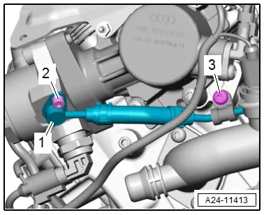
- Disconnect the connector -3-.
- Remove the bolt -2- on the retaining clamp.
 WARNING
The fuel system is under pressure.
Risk of injury from fuel spraying out.
- Wear protective eyewear.
- Wear safety gloves.
- Reduce the pressure: place clean cloths around the connection point and carefully open the connection point.
- Remove the union nut -1-.
- Remove the bolts -arrows-.
- Carefully remove the high pressure pump. The roller tappet can remain installed.

 Note
Note
Do not bend the high pressure line to a different angle.
Installing
Install in reverse order of removal and note the following:
 Note
Note
- Replace the O-rings after removing.
- The high pressure line connections must not show any signs of damage.
- Do not bend the high pressure line to a different angle.
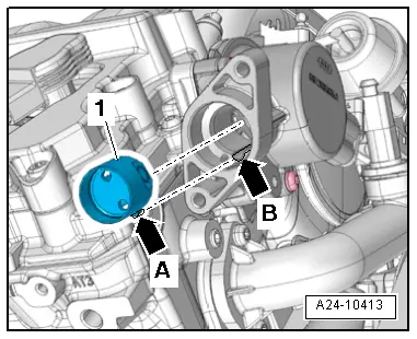
- Check the roller tappet -1- for damage and replace it if necessary.
- Coat the roller tappet with oil and insert it with the tab -arrow A- into the guide -arrow B-.
- Remove the front noise insulation. Refer to → Body Exterior; Rep. Gr.66; Noise Insulation; Noise Insulation, Removing and Installing.
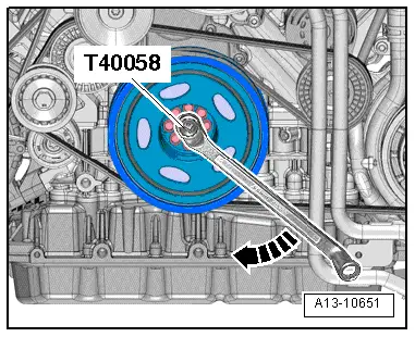
- Turn the crankshaft in the direction of engine rotation in direction of -arrow- using the Crankshaft Socket -T40058- and the offset open-end wrench. While doing so, push the roller tappet into the housing, until it has reached the lowest point.
- Only lift the high pressure line slightly to insert the high pressure pump.
- Push the high pressure pump downward by hand as far as possible until stop.
- While doing so tighten the bolts by hand.
- Tighten the bolts, procedure. Refer to → Fig. "High Pressure Pump - Tightening Specification and Sequence".
- Install the high pressure pipe. Refer to → Chapter "High Pressure Pipe, Removing and Installing".
- Install the engine cover. Refer to → Chapter "Engine Cover, Removing and Installing".
- Install the lock carrier cover. Refer to → Body Exterior; Rep. Gr.63; Front Bumper; Attachments, Removing and Installing.
- Check the fuel system for leaks. Refer to → Chapter "Fuel System Leak Test".
Tightening Specifications
- Refer to → Fig. "High Pressure Pump - Tightening Specification and Sequence"
- Refer to → Chapter "Overview - High Pressure Pump"
- Refer to → Chapter "Overview - Secondary Air Injection System"
- Refer to → Body Exterior; Rep. Gr.66; Noise Insulation; Overview - Noise Insulation.
High Pressure Pipe, Removing and Installing
Special tools and workshop equipment required
- Torque Wrench 1331 Insert - Open Jaw - 17mm -VAG1331/6-
Removing
- Remove the MPI injection fuel line. Refer to → Chapter "Fuel Line, Removing and Installing".
 WARNING
The fuel system is under pressure.
Risk of injury from fuel spraying out.
- Wear protective eyewear.
- Wear safety gloves.
- Reduce the pressure: place clean cloths around the connection point and carefully open the connection point.
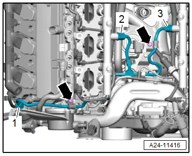
- Remove the union nuts -1, 2 and 3-. If required counterhold on the threaded connection.
- Remove the bolts -arrows-.
 Note
Note
- Do not bend the high pressure line to a different angle.
- If the connection -item 3- was loosened or removed, it must be replaced.
Installing
 Note
Note
- The high pressure line connections must not show any signs of damage.
- Do not bend the high pressure line to a different angle.
- Then tighten the union nut all the way by hand. While doing so, make sure the high pressure line is resting without tension.
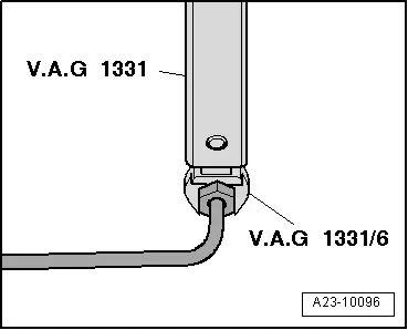
- Counterhold using an open end wrench at the threaded connection hex fitting on the fuel rail and tighten the union nut using a Torque Wrench 1331 5-50Nm -VAG1331- and a Torque Wrench 1331 Insert - Open Jaw - 17mm -VAG1331/6-.
- Only tighten the retaining strap bolt after the high pressure line has been tightened.
- Install the MPI injection fuel line. Refer to → Chapter "Fuel Line, Removing and Installing".
Tightening Specifications
- Refer to → Chapter "Overview - Intake Manifold Lower Section with Fuel Rail"
- Refer to → Chapter "Overview - High Pressure Pump"

