Audi Q7: Humidity Sensor in Fresh Air Intake Duct -G657-/ Air Quality Sensor -G238-, Removing and Installing
Air Quality Sensor -G238- with the Humidity Sensor In Fresh Air Intake Duct -G657-, Removing and Installing
 Note
Note
- There are different versions of the Air Quality Sensor -G238-/ Humidity Sensor in Fresh Air Intake Duct -G657--A-. Therefore, ensure the correct allocation. Refer to the Parts Catalog.
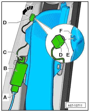
- Depending on the vehicle version, there are different fresh air intake versions. Refer to the Parts Catalog. Depending on the version of the fresh air intake the component location of the Air Quality Sensor -G238--C- (with the Humidity Sensor in Fresh Air Intake Duct -G657--D-) is different. Refer to → Chapter "Fresh Air Intake, Removing and Installing". This and the following illustrations show the Air Quality Sensor -G238--C- (with the Humidity Sensor in Fresh Air Intake Duct -G657--D-) for a fresh air intake version "1".
- On a vehicle with a "Mix" of "High" A/C system a sensor -A- is installed in which the Air Quality Sensor -G238--C- with the Humidity Sensor in Fresh Air Intake Duct -G657--D- are combined in a single component. Refer to the Parts Catalog and the Audi Sales Program.
- On a vehicle with a "Low" or "Mid" A/C system only a sensor -A- with a Humidity Sensor in Fresh Air Intake Duct -G657--D- but without an Air Quality Sensor -G238--C- is installed. Refer to the Parts Catalog and the Audi Sales Program.
- Sensor -A- (combination sensor with the Air Quality Sensor -G238- and the Humidity Sensor in Fresh Air Intake Duct -G657-) is a highly sensitive electronic component that can be damaged if it comes in direct contact with fluids, solvents, fuels and certain chemical compounds (for example, contaminants can enter through area -C or D-). Moreover, the function of the humidity sensor in fresh Air Intake Duct -G657- can be severely affected by direct contact with water so that correct moisture values can no longer be measured (briefly or permanently depending on the composition of the fluid). For this reason, do not install sensors that may have come into contact with these substances.
- Following removal, do not set down the Air Quality Sensor -G238- / Humidity Sensor in Fresh Air intake Duct -G657- in areas where it could come into contact with solvents, fuels or certain chemical compounds (liquids or vapors).

Removing and Installing
- Turn off the ignition.
- Remove the plenum chamber cover. Refer to → Body Interior; Rep. Gr.50; Bulkhead; Plenum Chamber Cover, Removing and Installing.
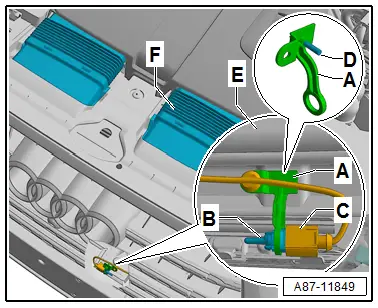
- Remove the outer cover for the fresh air intake box (rain water drain channel) -E-. Refer to → Chapter "Fresh Air Intake, Removing and Installing".
- Remove the Air Quality Sensor -G238- / Humidity Sensor in Fresh Air Intake Duct -G657--A- from the inner cover for the fresh air intake box -F-.
 Note
Note
So that with an installed plenum chamber cover no water runs via the outer fresh air intake box cover (rain water drain channel) -E- in the fresh air intake, the plenum chamber cover must not be damaged. In addition the plenum chamber cover must be correctly and completely engaged in the windshield frame.
- Disconnect the connector -B- from sensor -A-.
- Turn the Air Quality Sensor -G238- / Humidity Sensor in Fresh Air Intake Duct -G657--A- approximately 90º and remove it from the inner cover for the fresh air intake box -F-.
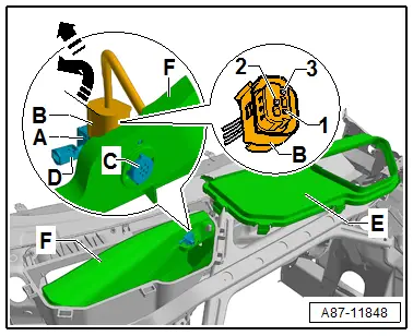
Terminal assignment in connector -B-
1 - Positive (terminal "15")
2 - Ground (terminal "31")
3 - Signal wire to the Front A/C Display Control Head -E87-. Refer to → Wiring diagrams, Troubleshooting & Component locations.
 Note
Note
- The signal from the Air Quality Sensor -G238- and the Humidity Sensor in Fresh Air intake Duct -G657- cannot be evaluated using service equipment.
- The data of the Air Quality Sensor -G238- and the Humidity Sensor in Fresh Air Intake Duct -G238- are evaluated by the Front A/C Display Control Head -E87-. Refer to Vehicle Diagnostic Tester in the "Guided Fault Finding" function. Refer to → Wiring diagrams, Troubleshooting & Component locations.
- The measured values of the Air Quality Sensor -G238- and the Humidity Sensor in Fresh Air Intake Duct -G657- are displayed in the "read measured values" function of the Guided Fault Finding of the Front A/C Display Control Head -E87-. For explanatory notes regarding the displays. Refer to Vehicle Diagnostic Tester in the "Guided Fault Finding" function.
Outside Air Temperature Sensor -G17-, Removing and Installing
 Note
Note
- The measured value of the outside Air Temperature Sensor -G17--B- is evaluated by the Vehicle Electrical System Control Module -J519- and is transmitted via the data bus to the Front A/C Display Control Head -E87- front A/C display control head (and the Instrument Cluster Control Module -J285-). Refer to Vehicle Diagnostic Tester in the "Guided Fault Finding" function and refer to → Wiring diagrams, Troubleshooting & Component locations.
- For a missing or incorrect measured value of the Outside Air Temperature Sensor -G17--B- certain heating and A/C system functions are no longer activated. Refer to Vehicle Diagnostic Tester"Guided Fault Finding" function.
Removing
- Turn off the ignition.
- Remove the cover on the lock carrier -F- and the left air intake motor. Refer to → Body Exterior; Rep. Gr.63; Front Bumper; Attachments, Removing and Installing.
 Note
Note
The bracket for the temperature sensor -A- depending on the version is either secured with an expanding clip -D- or with a bolt on the impact member of the bumper -E-.
- Disconnect the connector -C- from temperature sensor -B- and unclip the temperature sensor from bracket -A-.
Installing
Install in reverse order of removal. Note the following:
- After installing retrieve the DTC memory from the Front A/C Display Control Head -E87- (and the Vehicle Electrical System Control Module -J519-) and if necessary delete the displayed error. Refer to Vehicle Diagnostic Tester in the "Guided Fault Finding" function.
Driver Side Ionizer -J1105-, Removing and Installing
 Note
Note
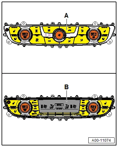
- The Driver Side Ionizer -J1105- is only intended for vehicles with an A/C system with a version -B-Front A/C Display Control Head - E87- and only for certain market specific vehicles. Refer to the Audi Sales Program.
- The Driver Side Ionizer -J1105- is installed in the air duct -F- to the left instrument panel vent (driver side).
- On vehicles without a Driver Side Ionizer -J1105- (and without a Driver Side Ionizer Button - E830-) if necessary seal the installation opening in the air duct -F- for example with air-tight adhesive tape.
- The Driver Side Ionizer Button -E830- is installed in the trim of the left instrument panel vent (On RHD vehicles in the right trim). Refer to → Chapter "Component Location Overview - Components Inside Front Passenger Compartment, Left Side of Passenger Compartment" and the vehicle Owner's Manual.
- Odors in the air flowing by are neutralized at ionizer -D-.
Removing
- Move the driver seat as far back as possible.
- Turn off the ignition.
- Remove the driver side instrument panel cover. Refer to → Body Interior; Rep. Gr.68; Storage Compartments and Covers; Driver Side Instrument Panel Cover, Removing and Installing.
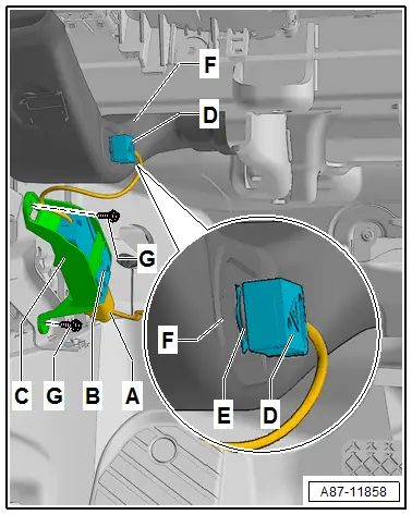
- Disconnect the connector -A-.
- Turn the ionizer -D- 90º and remove it from the mount in the air duct -F-.
- Remove the control module for the Driver Side Ionizer -J1105--B- from the bracket -C-.
 Note
Note
The bracket for the ionizer -C- is secured with two expanding rivets -G- on the instrument panel crossmember.

Installing
Install in reverse order of removal. Note the following:
- Check seal -E- for damage and proper seating.
- Retrieve the Front A/C Display Control Head -E87- DTC memory and if necessary delete the displayed error. Refer to Vehicle Diagnostic Tester in the "Guided Fault Finding" function.
Front Passenger Side Rear Ionizer -J1108-, Removing and Installing
 Note
Note
- The Front Passenger Side Rear Ionizer -J1108- is only installed on vehicles with a "High" A/C system and only for certain market specific vehicles. Refer to the Audi Sales Program. On vehicles without a Front Passenger Side Rear Ionizer -J1108- the installation opening in the air duct is sealed.
- The Front Passenger Side Rear Ionizer Button -E833- and the Front Passenger Side Rear Ionizer -J1108- are installed in the B-pillar behind the front passenger seat (on LHD vehicles in the right B-pillar).
- Odors in the air flowing by are neutralized at ionizer -D-.
- On vehicles without a Front Passenger Side Rear Ionizer Button -E833- (and Front Passenger Side Rear Ionizer -J1108-) if necessary close the installation opening in the air duct -F- for example with air-tight adhesive tape.
- The Front Passenger Side Rear Ionizer Button -E833- is installed in the trim panel on the right B-pillar. Refer to → Chapter "Component Location Overview - Components Inside Rear Passenger Compartment" and the vehicle Owner's Manual.
Removing
- Move the right front seat (passenger side seat) as far forward as possible.
- Turn off the ignition.
- Remove the upper trim of the right B-pillar. Refer to → Body Interior; Rep. Gr.70; Vehicle Interior Trim Panels; B-Pillar Trim Panel, Removing and Installing.
- Disengage and disconnect the connector -A-.
- Remove the bolt -C-.
- Turn the ionizer -D- 90º in direction of -arrow- and remove it from the mount of air duct -F-.

Installing
Install in reverse order of removal. Note the following:
- Check seal -E- for damage and proper seating.
- Check the event memory of the front A/C display control head, the Front A/C Display Control Head -E87- (and the Rear A/C Display Control Head -E265-) and erase any displayed malfunctions. Refer to Vehicle Diagnostic Tester in the "Guided Fault Finding" function if necessary.

