Audi Q7: Refrigerant line, Disconnecting and Connecting
Information on the Refrigerant Lines and A/C Compressor
 Caution
Danger due to refrigerant coming out under pressure.
Danger of frost bite to skin and other parts of the body.
Only loosen the connection point bolts when the refrigerant circuit is empty.
 Note
Note
- On most vehicles the A/C compressor is always driven when the engine is running, it doesn't always have a A/C Clutch -N25-. Therefore the engine may only be started when the refrigerant circuit has been properly assembled. For example; if the refrigerant lines are not connected to A/C compressor, when the engine is running the A/C compressor may heat up (via internal heat generation) so much that the A/C compressor will be damaged. Such internal heat generation results from the fact that - even with delivery near 0% - the compressor is confronted with a fixed resistance (sealed circuit).
- Close open lines and connections on A/C compressor using suitable caps (to prevent possible penetration of dirt and moisture).
Connection Points of Refrigerant Lines, Loosening and Assembling
 Caution
This procedure contains mandatory replaceable parts. Refer to component overview prior to starting procedure.
Mandatory Replacement Parts
- O-ring - Pass-Through for the Refrigerant Lines in the Vehicle Interior to Refrigerant Line - Low Pressure Side
- O-ring - Rear Expansion Valve to Refrigerant Line - High Pressure Side
- O-ring - Rear Expansion Valve to Refrigerant Line - Low Pressure Side
- O-ring - Refrigerant Line - High Pressure Side
- O-ring - Refrigerant Line - Low Pressure Side
 Caution
Danger due to refrigerant coming out under pressure.
Danger of frost bite to skin and other parts of the body.
Only loosen the connection point bolts when the refrigerant circuit is empty.
 Note
Note
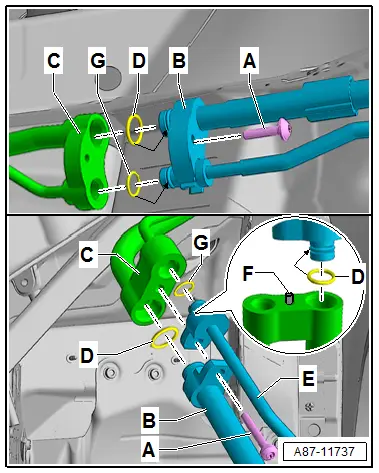
- The procedure for loosening applies to all connection points in the refrigerant circuit and for the branching point of refrigerant lines to rear heater and A/C unit. There are differences in diameter for line connections, versions of O-ring seals and mounting bolts.
- Depending on component location, various components in vicinity of connection points must be loosened or removed to be able to disconnect the connection point.
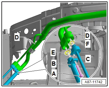
- The following illustration shows as an example the connection points between the refrigerant lines from the inner heat exchanger to the A/C compressor and to the condenser as well as the connection points on the opening in the perform to the refrigerant lines to the evaporator in the rear heater and A/C unit. These connection points are installed in the area under the left front fender.
Loosening
- Turn off the ignition.
- Discharge the refrigerant circuit. Refer to → Refrigerant R134a Servicing; Rep. Gr.87; Refrigerant Circuit.
- To loosen the connection locations remove the front left wheel housing liner. Refer to → Body Exterior; Rep. Gr.66; Wheel Housing Liner; Front Wheel Housing Liner, Removing and Installing (for accessibility to the illustrated connection point).
- Remove the bolts -A-.
- Disconnect the connection point of refrigerant lines -B, E and C-.
 Note
Note
Immediately seal off any open line connections and connection points with clean plugs, for example, taken from the Engine Bung Set -VAS6122-.
Assembling
Assemble in the reverse order of removal. Note the following:
- Replace the O-rings -D and G-, they have different versions. Refer to the Parts Catalog.
- Thoroughly clean the refrigerant lines around the connection area and check for damage.
- If equipped inspect the alignment pin -F- (not present on all connections) for damage and make sure that it is seated correctly.
 Note
Note
- Coat the O-ring seals lightly with refrigerant oil prior to installation. Refer to → Chapter "Refrigerant Circuit Seals".
- Note the different tightening specifications of bolts -A-.
- Tightening specification of bolts -A- with a thread "M6" 9 Nm.
- Tightening specification of bolts -A- with a thread "M8" 20 Nm.
- Check the routing of the refrigerant lines after attachment. They must be inserted in the provided brackets in a tension-free manner and must not come in contact with other components.
- Reinstall removed components in the reverse order and reattach detached components.
- Evacuate and charge the refrigerant circuit. Refer to → Refrigerant R134a Servicing; Rep. Gr.87; Refrigerant Circuit.
- Retrieve the Front A/C Display Control Head -E87- DTC memory and if necessary delete the displayed error. Refer to Vehicle Diagnostic Tester in the "Guided Fault Finding" function.
- Operate the A/C system after charging the refrigerant circuit. Refer to → Chapter "A/C System, Starting after Charging Refrigerant Circuit".
 Note
Note
Note the information regarding operating the A/C system after filling. Refer to → Refrigerant R134a Servicing; Rep. Gr.87; A/C System, General Information.
Plenum Chamber Refrigerant Line Pass-Through, Removing and Installing
 Caution
This procedure contains mandatory replaceable parts. Refer to component overview prior to starting procedure.
Mandatory Replacement Parts
- O-ring - Refrigerant Line - High Pressure Side
- O-ring - Refrigerant Line - Low Pressure Side
- O-ring - Refrigerant Line - High Pressure Side to Pass-Through for Refrigerant Lines in the Plenum Chamber
- O-ring - Refrigerant Line - Low Pressure Side to Pass-Through for Refrigerant Lines in the Plenum Chamber
 Caution
Danger due to refrigerant coming out under pressure.
Danger of frost bite to skin and other parts of the body.
Only loosen the connection point bolts when the refrigerant circuit is empty.
Removing
- Turn off the ignition.
- Discharge the refrigerant circuit. Refer to → Refrigerant R134a Servicing; Rep. Gr.87; Refrigerant Circuit.
- Remove the left front wheel housing liner. Refer to → Body Exterior; Rep. Gr.66; Wheel Housing Liner; Front Wheel Housing Liner, Removing and Installing.
- Remove the windshield wiper motor. Refer to → Electrical Equipment; Rep. Gr.92; Windshield Wiper System; Windshield Wiper Motor V, Removing and Installing.
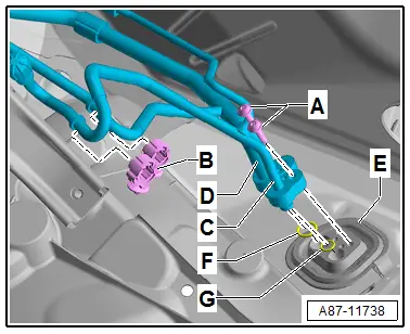
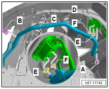
- Remove the bolts -A-. Refer to → Chapter "Overview - Refrigerant Lines in Plenum Chamber and Front Expansion Valve" for the tightening specification.
- Loosen both refrigerant lines to the expansion valve -C and D- from the bracket -B- and the pass-through -E-.
 Note
Note
Immediately seal off any open line connections and connection points with clean plugs, for example, taken from the Engine Bung Set -VAS6122-.
For Vehicles with A Second Evaporator (a rear heater and A/C unit)
- Remove the bolt -A-. Refer to → Chapter "Overview - Expansion Valve and Refrigerant Lines to Rear Heater and A/C Unit" for the tightening specification.
- Loosen both refrigerant lines to the second evaporator -C and D- from the line connection -B- to the pass-through -E-.
All Vehicles
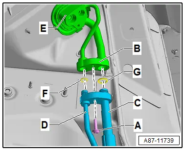
- Remove the bolt -A-. Refer to → Chapter "Overview - Inner Heat Exchanger and Components under Front Left Fender" for the tightening specification.
- Loosen the inner heat exchanger -C- from the bracket -B- and the pass-through -D-.

- Loosen the pass-through -A or B- (different versions) from the opening in the body, to so do press the catches.
Installing
Install in reverse order of removal. Note the following:
- Check the grommet -C- of the pass-through (-A or B-) for damage and correct seating on the pass-through and the opening in the body.
- Replace all O-rings (in this illustration -E and F-) there are different versions. Refer to the Parts Catalog.
 Note
Note
- Coat the O-ring seals lightly with refrigerant oil prior to installation. Refer to → Chapter "Refrigerant Circuit Seals".
- Pay attention to the different bolt tightening specifications (in this illustration -A-).
- Thoroughly clean the pass-through -D- and the refrigerant lines around the connection area and check for damage.
- Tightening specification of bolts -A- with a thread "M6" 9 Nm.
- Tightening specification of bolts -A- with a thread "M8" 20 Nm.
- Check the routing of the refrigerant lines after attachment. They must be inserted in the provided brackets in a tension-free manner and must not come in contact with other components.
- Reinstall removed components in the reverse order and reattach detached components.
- Evacuate and charge the refrigerant circuit. Refer to → Refrigerant R134a Servicing; Rep. Gr.87; Refrigerant Circuit.
- Retrieve the Front A/C Display Control Head -E87- DTC memory and if necessary delete the displayed error. Refer to Vehicle Diagnostic Tester in the "Guided Fault Finding" function.
- Operate the A/C system after charging the refrigerant circuit. Refer to → Chapter "A/C System, Starting after Charging Refrigerant Circuit".

 Note
Note
Note the information regarding operating the A/C system after filling. Refer to → Refrigerant R134a Servicing; Rep. Gr.87; A/C System, General Information.
Refrigerant Lines with Inner Heat Exchanger, Removing and Installing
 Caution
This procedure contains mandatory replaceable parts. Refer to component overview prior to starting procedure.
Mandatory Replacement Parts
- O-ring - High Pressure Side Refrigerant Line to Refrigerant Line with Inner Heat Exchanger
 Caution
Danger due to refrigerant coming out under pressure.
Danger of frost bite to skin and other parts of the body.
Only loosen the connection point bolts when the refrigerant circuit is empty.
Removing
- Turn off the ignition.
- Discharge the refrigerant circuit. Refer to → Refrigerant R134a Servicing; Rep. Gr.87; Refrigerant Circuit.
- Remove the left front wheel housing liner. Refer to → Body Exterior; Rep. Gr.66; Wheel Housing Liner; Front Wheel Housing Liner, Removing and Installing.
- Remove the bolt -A-. Refer to → Chapter "Overview - A/C Compressor and Condenser" for the tightening specification.
- Remove refrigerant lines -B and C- (in the area under the left headlamp) from refrigerant line with inner heat exchanger -D- .
 Note
Note
Immediately seal off any open line connections and connection points with clean plugs, for example, taken from the Engine Bung Set -VAS6122-.
- Remove the bolt -A-. Refer to → Chapter "Overview - Inner Heat Exchanger and Components under Front Left Fender" for the tightening specification.
- Loosen the inner heat exchanger -C- from the bracket -B- and the pass-through -D-.

Installing
Installation is done is reverse order, observe the following:
- Replace all O-rings (in this illustration -E and F-) there are different versions. Refer to the Parts Catalog.
 Note
Note
- Coat the O-ring seals lightly with refrigerant oil prior to installation. Refer to → Chapter "Refrigerant Circuit Seals".
- Pay attention to the different bolt tightening specifications (in this illustration -A-).
- Always clean the inner heat exchanger, pass-through, and refrigerant lines on the connection area and check them for damage.
 Note
Note
Install the refrigerant lines such that they are not strained.
- Check the routing of the refrigerant lines after attachment. They must be inserted in the provided brackets in a tension-free manner and must not come in contact with other components.
- Reinstall removed components in the reverse order and reattach detached components.
- Install the remaining removed components.
- Evacuate and charge the refrigerant circuit. Refer to → Refrigerant R134a Servicing; Rep. Gr.87; Refrigerant Circuit.
- Turn on the ignition.
- Retrieve the Front A/C Display Control Head -E87- DTC memory and if necessary delete the displayed error. Refer to Vehicle Diagnostic Tester in the "Guided Fault Finding" function.
- Operate the A/C system after charging the refrigerant circuit. Refer to → Chapter "A/C System, Starting after Charging Refrigerant Circuit".
 Note
Note
Note the information regarding operating the A/C system after filling. Refer to → Refrigerant R134a Servicing; Rep. Gr.87; A/C System, General Information.

