Audi Q7: Ignition/Glow Plug System
Ignition System
Overview - Ignition System
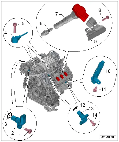
1 - Bolt
- 9 Nm
2 - Camshaft Position Sensor
- Cylinder Bank 1 (Right)
- Intake side: Camshaft Position Sensor -G40-
- Exhaust side Camshaft Position Sensor 3 -G300-
- Removing and installing. Refer to → Chapter "Camshaft Position Sensor, Removing and Installing".
3 - O-Ring
- Replace after removing
4 - Knock Sensor
- Cylinder bank 1 (right) Knock Sensor 1 -G61-
- Cylinder bank 2 (left) Knock Sensor 2 -G66-
- The contact surfaces between the knock sensor and cylinder block must be free of corrosion, dirt and grease.
- Removing and installing. Refer to → Chapter "Knock Sensor, Removing and Installing".
5 - Bolt
- 25 Nm
6 - Spark Plug
- Remove and install with the Spark Plug Removal Tool -3122B-.
- Tightening specification.
- Replacement interval. Refer to Maintenance Tables.
7 - Ignition Coil with Power Output Stage
- Ignition Coil 1 with Power Output Stage -N70-
- Ignition Coil 2 with Power Output Stage -N127-
- Ignition Coil 3 with Power Output Stage -N291-
- Ignition Coil 4 with Power Output Stage -N292-
- Ignition Coil 5 with Power Output Stage -N323-
- Ignition Coil 6 with Power Output Stage -N324-
- Removing and installing. Refer to → Chapter "Ignition Coils with Power Output Stages, Removing and Installing".
8 - Bolt
- 5 Nm
9 - Wiring Harness
10 - Engine Speed Sensor -G28-
- Removing and installing. Refer to → Chapter "Engine Speed Sensor -G28-, Removing and Installing".
11 - Bolt
- 9 Nm
12 - O-Ring
- Replace after removing
13 - Camshaft Position Sensor
- Cylinder Bank 2 (Left)
- Intake side Camshaft Position Sensor 2 -G163-
- Exhaust side: Camshaft Position Sensor 4 -G301-
- Removing and installing. Refer to → Chapter "Camshaft Position Sensor, Removing and Installing".
14 - Bolt
- 9 Nm
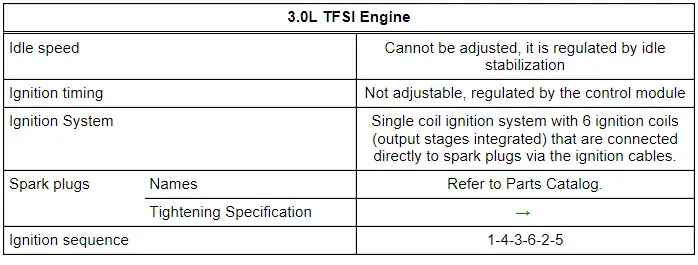
Test Data and Spark Plugs
Ignition Coils with Power Output Stages, Removing and Installing
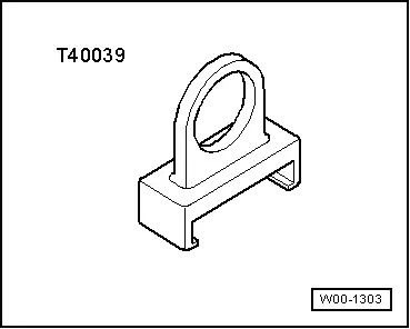
Special tools and workshop equipment required
- Puller - Ignition Coil -T40039-
Removing
- Remove the air filter upper section. Refer to → Chapter "Air Filter Housing, Removing and Installing".
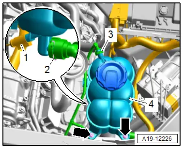
Cylinder Bank 2 (Left):
- Remove the bolts -arrows- and remove the coolant expansion tank -4- upward from the bracket.
- Disconnect the connector -1-.
- Move the coolant reservoir to the side with the hoses -2 and 3- still attached.
Continuation for Both Sides:
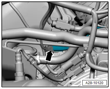
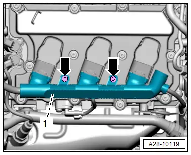
- Remove the bolts -arrows- and disconnect the connectors on the ignition coils.
- Lay the wiring harness -1- slightly underneath.

 Note
Note
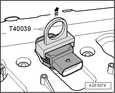
The installation position for cylinder bank 2 (left) is shown in the illustration.
 Note
Note
- To remove the ignition coils, place the Puller - Ignition Coil -T40039- on topmost thick rib -arrow- of ignition coil with power output stage.
- The lower ribs may be damaged if they are used.
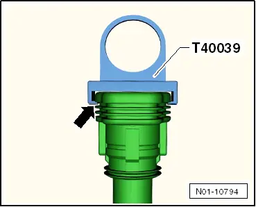
- Remove the ignition coil in direction of -arrow-.
Installing
Install in reverse order of removal and note the following:
- Install the air filter upper section. Refer to → Chapter "Air Filter Housing, Removing and Installing".
Tightening Specifications
- Refer to → Chapter "Overview - Ignition System"
Knock Sensor, Removing and Installing
Removing
Cylinder Bank 1 (Right):
- Remove the cylinder "2" FSI fuel injector. Refer to → Chapter "Fuel Injectors, Removing and Installing, FSI Fuel Injection".
- Remove the connector -arrow- from the bracket, disconnect it, and free up the wire.
Cylinder Bank 2 (Left):
- Remove the cylinder "5" FSI fuel injector. Refer to → Chapter "Fuel Injectors, Removing and Installing, FSI Fuel Injection".
- Remove the connector -arrow- from the bracket, disconnect it, and free up the wire.
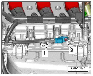
Continuation for Both Sides:
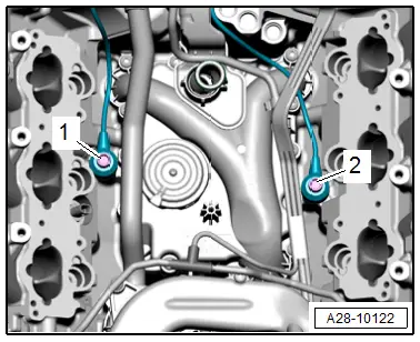
- Remove the bolt -1- for Knock Sensor 1 -G61- or the bolt -2- for the Knock Sensor 2 -G66- and then remove the knock sensor.
Installing
Install in reverse order of removal and note the following:
- Install the FSI fuel injector. Refer to → Chapter "Fuel Injectors, Removing and Installing, FSI Fuel Injection".
Tightening Specifications
- Refer to → Chapter "Overview - Ignition System"
Camshaft Position Sensor, Removing and Installing
Camshaft Position Sensor -G40-, Removing and Installing
 Caution
This procedure contains mandatory replaceable parts. Refer to component overview prior to starting procedure.
Mandatory Replacement Parts
- O-ring - Camshaft position sensor
Removing
- Remove the engine cover. Refer to → Chapter "Engine Cover, Removing and Installing".
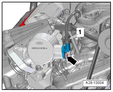
- Disconnect the connector -1- on cylinder bank 1.
- Remove the bolt -arrow- and the Camshaft Position Sensor -G40-.
Installing
Install in reverse order of removal and note the following:
 Note
Note
Replace the O-ring after removing.
- Install the engine cover. Refer to → Chapter "Engine Cover, Removing and Installing".
Tightening Specifications
- Refer to → Chapter "Overview - Ignition System"
Camshaft Position Sensor 2 -G163-, Removing and Installing
 Caution
This procedure contains mandatory replaceable parts. Refer to component overview prior to starting procedure.
Mandatory Replacement Parts
- O-ring - Camshaft position sensor
Removing
- Remove the engine cover. Refer to → Chapter "Engine Cover, Removing and Installing".
- Disconnect the connector -1- on cylinder bank 2.
- Remove the bolt -arrow- and the Camshaft Position Sensor 2 -G163-.
Installing
Install in reverse order of removal and note the following:
 Note
Note
Replace the O-ring after removing.
- Install the engine cover. Refer to → Chapter "Engine Cover, Removing and Installing".
Tightening Specifications
- Refer to → Chapter "Overview - Ignition System"
Camshaft Position Sensor 3 -G300-, Removing and Installing
 Caution
This procedure contains mandatory replaceable parts. Refer to component overview prior to starting procedure.
Mandatory Replacement Parts
- O-ring - Camshaft position sensor
Removing
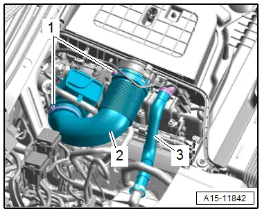
- Loosen the hose clamps -1- and remove the air duct pipe -2-.
 Note
Note
Ignore -3-.
- Disconnect the connectors -1- on the camshaft adjustment valves.
 Note
Note
Ignore -2-.
- Remove the bolts -arrows- and disconnect the connectors on the ignition coils.
- Press the wiring harness upward slightly.
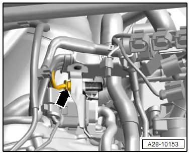
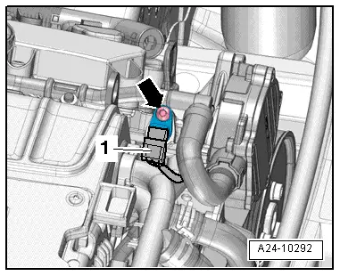
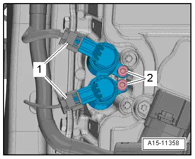
- Disconnect the connector -1-.
- Remove the bolt -2- and remove the camshaft position sensor.
 Note
Note
The installation position for the Camshaft Position Sensor 4 -G301- on cylinder bank 2 (left) is shown.
Installing
Install in reverse order of removal and note the following:
 Note
Note
- Replace the O-ring after removing.
- Secure all hose connections with hose clamps that match the ones used in series production. Refer to the Parts Catalog.
Tightening Specifications
- Refer to → Chapter "Overview - Ignition System"
- Refer to → Chapter "Overview - Charge Air Hose Connections"
Camshaft Position Sensor 4 -G301-, Removing and Installing
 Caution
This procedure contains mandatory replaceable parts. Refer to component overview prior to starting procedure.
Mandatory Replacement Parts
- O-ring - Camshaft position sensor
Removing
- Remove the air filter upper section. Refer to → Chapter "Air Filter Housing, Removing and Installing".
- Disconnect the connector -1-.
- Remove the bolt -2- and remove the camshaft position sensor.

Installing
Install in reverse order of removal and note the following:
 Note
Note
Replace the O-ring after removing.
- Install the air filter upper section. Refer to → Chapter "Air Filter Housing, Removing and Installing".
Tightening Specifications
- Refer to → Chapter "Overview - Ignition System"
Engine Speed Sensor -G28-, Removing and Installing
Removing
- Remove the rear noise insulation. Refer to → Body Exterior; Rep. Gr.66; Noise Insulation; Noise Insulation, Removing and Installing.
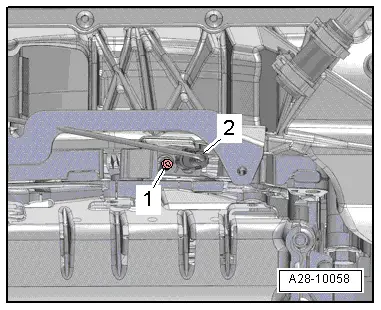
- Disconnect the connector -2-.
- Remove the bolt -1- and the Engine Speed Sensor -G28-.
Installing
Install in reverse order of removal.
Tightening Specifications
- Refer to → Chapter "Overview - Ignition System"
- Refer to → Body Exterior; Rep. Gr.66; Noise Insulation; Overview - Noise Insulation.
Special Tools
Special tools and workshop equipment required
- Puller - Ignition Coil -T40039-
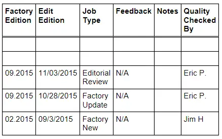
Revision History
DRUCK NUMBER: A0Q5A020921
Oil Gauge Tester T40178 Service Values
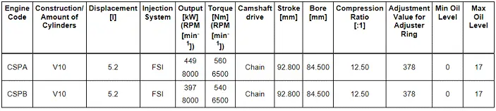
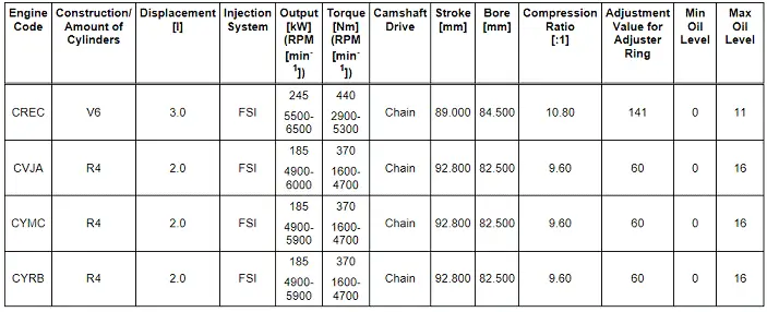
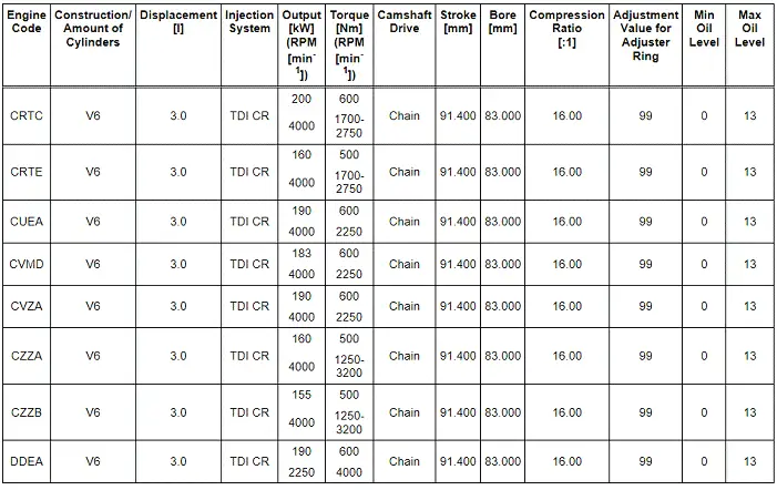
Engine Overview with Adjustment Values, Gauge - Oil Gauge Tester (T40178)
Audi Q7 - Model Code 4M
Gasoline Engines
Diesel Engines
Audi R8 - Model Code 4S
Gasoline Engines