Audi Q7: Lane Change Assistance
Overview - Lane Change Assistance
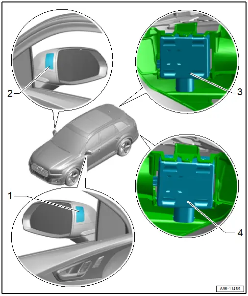
1 - Lane Change Assistance Warning Lamp in Driver Exterior Rearview Mirror -K233-
- Removing and installing. Refer to → Chapter "Lane Change Assistance Warning Lamp In Driver and Front Passenger Exterior Rearview Mirror -K233-/-K234-, Removing and Installing".
2 - Lane Change Assistance Warning Lamp in Front Passenger Exterior Rearview Mirror -K234-
- Removing and installing. Refer to → Chapter "Lane Change Assistance Warning Lamp In Driver and Front Passenger Exterior Rearview Mirror -K233-/-K234-, Removing and Installing".
3 - Lane Change Assistance Control Module -J769-
- Removing and installing. Refer to → Chapter "Lane Change Assistance Control Module -J769-/-J770-, Removing and Installing".
- Calibrating. Refer to → Chapter "Lane Change Assistance, Calibrating".
4 - Lane Change Assistance Control Module 2 -J770-
- Removing and installing. Refer to → Chapter "Lane Change Assistance Control Module -J769-/-J770-, Removing and Installing".
- Calibrating. Refer to → Chapter "Lane Change Assistance, Calibrating".
Lane Change Assistance Warning Lamp In Driver and Front Passenger Exterior Rearview Mirror -K233-/-K234-, Removing and Installing
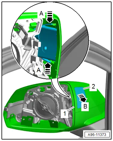
Removing
- Remove the mirror trim. Refer to → Body Exterior; Rep. Gr.66; Exterior Rearview Mirror; Mirror Trim, Removing and Installing.
- Release the catches in direction of -A arrows- and remove the warning lamp -2- from the mirror cap -1- in direction of -arrow B-.
- Disconnect the connector.
Installing
Install in the reverse order of removal while noting the following:
- If an LED is faulty, the entire lane change assistance warning lamp in the exterior rearview mirror must be replaced.
Lane Change Assistance Control Module -J769-/-J770-, Removing and Installing
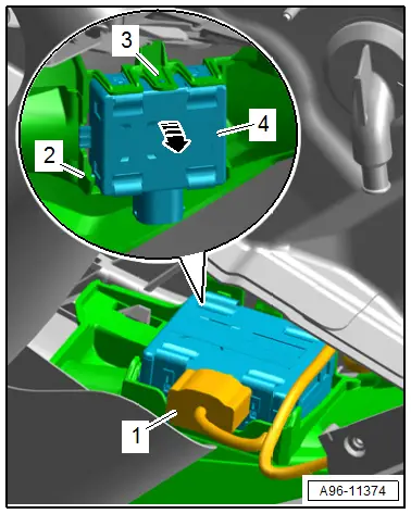
Removing
- Grasp behind the bumper cover and disconnect the connector -1-.
- Release the catch -3- and pivot out the control module -4- in direction of -arrow-.
- Disengage and remove the control module from the lower mount -2-.
Installing
Install in the reverse order of removal while noting the following:
- Calibrate the Lane Change Assistance Control Modules -J769-/-J770-. Refer to → Chapter "Lane Change Assistance, Calibrating".
Lane Change Assistance, Calibrating
Special tools and workshop equipment required
- Calibration Unit -VAS6350A-
- When a software update should be made, this must be performed before the calibration.
Conditions
- The Lane Change Assistance Control Modules -J769-/-J770- must be calibrated in the "Guided Fault Finding" or "Guided Functions" operating mode under the following conditions. Refer to Vehicle Diagnostic Tester:
- Lane Change Assistance Control Module -J769- or Lane Change Assistance Control Module 2 -J770- was replaced.
- The rear bumper cover was damaged by a parking block, for example.
- The rear bumper cover was removed and installed.
- The threaded connections on the bumper mount are loosened.
- "No or incorrect basic setting/adaptation" is stored in the DTC memory.
Preparing for Calibration
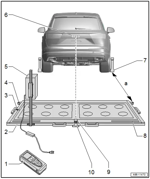
1 - Calibration Tool - Spacing Laser -VAS6350/2-
- For distance measurement
- Usage information. Refer to the Owner's Manual.
2 - Calibration Unit -VAS6350A-
3 - Level
- On the Calibration Unit -VAS6350A-
- To check the horizontal position of the Calibration Unit -VAS6350A-
4 - Catch Bracket
- To mount the Calibration Tool - Spacing Laser Calibration Tool - Spacing Laser -VAS6350/2- for the distance measurement
- Distance to the Calibration Tool - Wheel Center Mountings -VAS6350/1- on the rear wheels: dimension -a- = 1700 +- 2 mm
5 - Calibration Tool - Lane Change Calibration Tool -VAS6350/4-
- Is moved from one side of the measuring field to the other during calibration
- When installed correctly, the vehicle electrical system voltage line must be connected at lower left of the calibration device (as seen in direction of travel)
6 - Brand Emblem
- The laser point is aligned to the center of the brand emblem
7 - Calibration Tool - Wheel Center Mountings -VAS6350/1-
- With wheel bolt adapter and measuring paddle
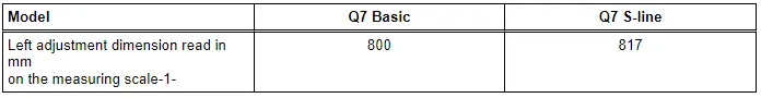
8 - Measuring Scale
- For positioning the Calibration Tool - Lane Change Calibration Tool -VAS6350/4-
9 - Calibration Tool - Linear Laser -VAS6350/3-
- With "laser protective eyewear"
- On the Calibration Unit -VAS6350A-
- Switching on and off. Refer to Owner's Manual.
10 - Plastic Foot
- Quantity: 3
- Can be adjusted when setting the horizontal position of the Calibration Unit -VAS6350A-
Preliminary Work
- Move the vehicle onto a solid, flat surface.
- On vehicles with air suspension activate the "standard vehicle height" (MMI air suspension: comfort or radio).
- Apply the parking brake - the vehicle must not move during the measurement.
- Place the front wheels in a straight-ahead position - steering wheel in neutral position.
- Connect the Vehicle Diagnostic Tester.
TIP
If a malfunction message appears in the display. Refer to the Vehicle Diagnostic Tester.
- Turn on the ignition.
- Remove the label with the metal foil from the bumper cover, if necessary.
- Secure three suitable wheel bolt adapters for the wheel bolts on each Calibration Tool - Wheel Center Mountings -VAS6350/1-.
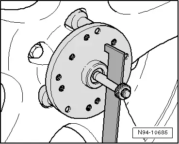
- Insert the measuring paddle at both Calibration Tool - Wheel Center Mountings -VAS6350/1- and secure with the locking nut.
- Place the Calibration Tool - Wheel Center Mountings -VAS6350/1- onto the wheel bolts on both rear wheels.
- The wheel center mounting rotation center must be in the wheel rotation center.
- Place the Calibration Tool - Wheel Center Mountings -VAS6350/1- on the wheels so that the "anti-theft wheel bolts" are not connected to the wheel center mounting.
- Adjust the measuring paddle using the locking nuts so that they move freely just above the floor.
- The measuring paddles must move easily.
- The measuring paddles must be vertical.
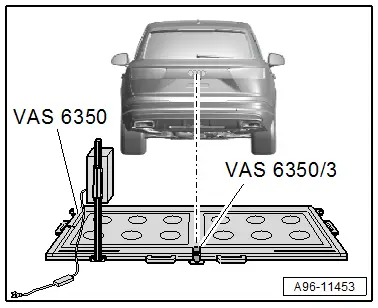
- Position the Calibration Unit -VAS6350A- at distance -a- to the rear wheels.
- Dimension -a- = 1,700 mm
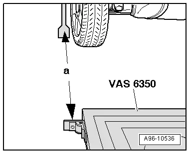
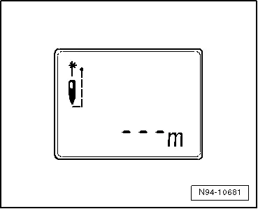
- Switch on the Calibration Tool - Spacing Laser -VAS6350/2- with the ON button.
Display on the Calibration Tool - Spacing Laser -VAS6350/2-:
- "- - - m"
- The laser is switched on at same time.
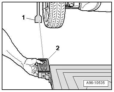
- For distance measurement, hold the Calibration Tool - Spacing Laser -VAS6350/2--2- flush to the left catch bracket as shown.
- The Calibration Tool - Spacing Laser -VAS6350/2- must lie firmly against the catch bracket.
- Make sure the "laser beam" for the distance measurement contacts the enlarged lower part on the paddle -1-.
If this is not the case, measuring paddle height must be corrected using locking nuts on Calibration Tool - Wheel Center Mountings -VAS6350/1-.
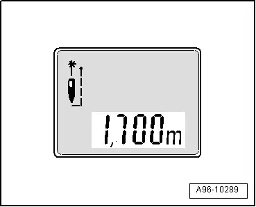
- Briefly press the ON button for distance measurement.
Display on the Calibration Tool - Spacing Laser -VAS6350/2-:
- "1,700 m" (specified value: 1700 +- 2 mm).
- Repeat the measuring procedure from the right stop bracket to the right rear wheel.
- The distance value must be the same on both sides.
If both measured values are not the same, adjust the Calibration Unit -VAS6350A- accordingly.
Calibrating
The Vehicle Diagnostic Tester is connected.
- Select the Diagnostic mode and start.
- Select the Test plan tab.
- Press the Select individual tests button and select the following one after the other:
- Body
- Electrical Equipment
- 01 - OBD-capable systems
- 3C - Lane Change Assistance Control Module -J769
- 3C - Lane change assistance control module, functions
- 3C - Calibration
- Start the selected program and follow the instructions in the Vehicle Diagnostic Tester display.
TIP
The following information clarifies which version of the lane change assistance is installed in the vehicle (SWA3.0).
This information for adjusting the calibration device is important for later steps in the procedure to avoid malfunctions.
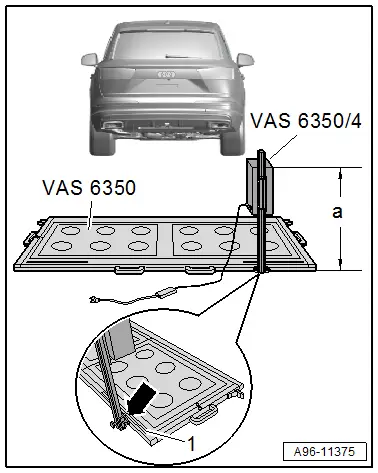
- Secure the Calibration Tool - Lane Change Calibration Tool -VAS6350/4- to the Calibration Unit -VAS6350A- mount on the rear left.
- When installed correctly, the vehicle electrical system voltage wire must be connected at the bottom left of the calibration device (as seen in direction of travel).
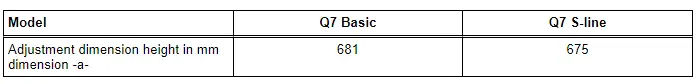
Dimension -a- is measured from the upper edge of the calibration device to the floor.
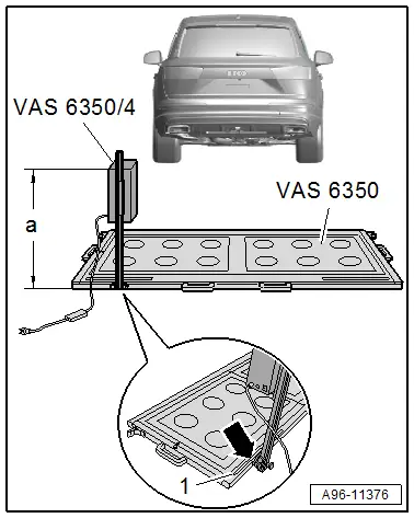
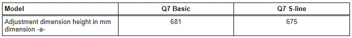
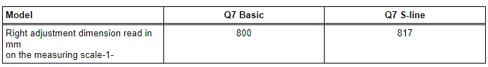
- The indicator on the base of the Calibration Tool - Lane Change Calibration Tool Calibration Tool - Lane Change Calibration Tool -VAS6350/4- must align with adjustment dimension on the measuring scale -1- on measuring field -arrow-.
- Connect the Calibration Tool - Lane Change Calibration Tool Calibration Tool - Lane Change Calibration Tool -VAS6350/4- to the vehicle electrical system voltage.
- Bring the Calibration Unit -VAS6350A- into a horizontal position by turning the plastic feet.
- Observe the bubble level (sight glass) on the Calibration Unit -VAS6350A--arrow-.
- Turn on the Calibration Laser -VAS6350/3A- on the Calibration Unit -VAS6350A-.
- Wear "laser protective eyewear".
- Align the Calibration Unit -VAS6350A- so that the Calibration Tool - Linear Laser -VAS6350/3- strikes the center of the brand emblem on the rear lid.
- Check the distance on the left and right sides between the catch brackets of the Calibration Unit -VAS6350A- and the measuring paddles -1- on wheel mountings again.
- Specified value: 1700 +- 2 mm
Calibration Procedure
The following should not occur during the calibration procedure:
- There must be no metal reflectors within a 2 m radius of the calibration device (for example, tool carts, metal cabinets).
- Vehicle doors must not be opened or closed.
- People must not sit in the vehicle.
- People must not go between the vehicle and the Calibration Tool - Lane Change Calibration Tool -VAS6350/4-.

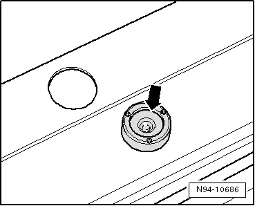
Procedure
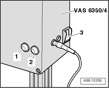
- Turn on the Calibration Tool - Lane Change Calibration Tool -VAS6350/4- at the power switch -3-.
- The green LED -1- must turn on.
- If the red LED -2- comes on: Check the -VAS 6350/4-.
- Follow the instructions in the vehicle diagnostic tester display.

During the program sequence, there is a prompt to switch the Calibration Tool - Lane Change Calibration Tool -VAS6350/4- from the left to the right side of the Calibration Tool -VAS6350-.
- Turn off the Calibration Tool - Lane Change Calibration Tool -VAS6350/4- and reposition the calibration tool.
- When installed correctly, the vehicle electrical system voltage wire must be connected at the bottom left of the calibration device (as seen in direction of travel).
Dimension -a- is measured from the upper edge of the calibration device to the floor.
- The indicator on the base of the Calibration Tool - Lane Change Calibration Tool -VAS6350/4- must align with adjustment dimension on the measuring scale -1- on measuring field -arrow-.
- Turn on the Calibration Tool - Lane Change Calibration Tool -VAS6350/4- at the power switch -3-.
- The green LED -1- must turn on.
- Follow the instructions in the vehicle diagnostic tester display.
- After calibrating the lane change assistance successfully, end "calibration", switch off the ignition and disconnect the diagnostic connector.