Audi Q7: Driver Assistance Systems Front Camera
Component Location Overview - Driver Assistance Systems Front Camera
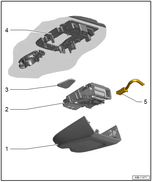
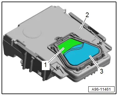
1 - Cover
2 - Driver Assistance Systems Front Camera -R242-
- Removing and installing. Refer to → Chapter "Driver Assistance Systems Front Camera, Removing and Installing".
- Replacing. Refer to → Chapter "Driver Assistance Systems Front Camera, Replacing".
3 - Silicone Pad
- Replace after removal
4 - Baseplate
- Cannot be separated from the windshield
5 - Connector
Driver Assistance Systems Front Camera, Removing and Installing
Driver Assistance Systems Front Camera, Removing and Installing
Special tools and workshop equipment required
- Angled Screwdriver -VAS6416-
- Cleaning Solution -D 009 401 04-
Removing
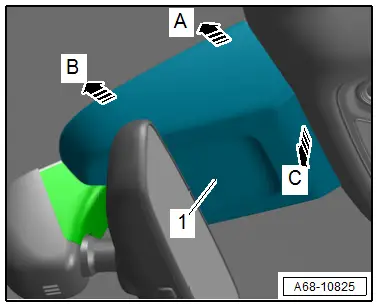
- Unclip the cover -1- in direction of -A, B and C arrows- with the Angled Screwdriver -VAS6416- to do so carefully guide a long reach special wrench for the flat-head screws between the windshield and the cover.
- Repeat the procedure on the opposite side.
- Disengage the front cover and remove toward the rear.
- Free up the wire if necessary.
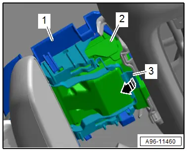
- Release the securing clip -3--arrow- and remove the driver assistance systems front camera -2- from the mount -1-.
- Disconnect the connector.
Installing
Install in the reverse order of removal while noting the following:
- Replace the silicon pad.
- The camera field of vision on the inside of the windshield must not be fogged up or dirty.
- Any silicone residue must be completely removed.
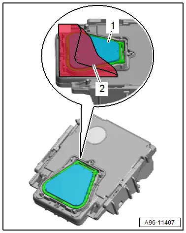
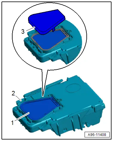
- Remove the silicone pad -3- from the front camera -2- without leaving any residue.
- Clean the adhesive surface -1- on the front camera with Cleaning Solution -D 009 401 04-.
- Remove the silicone paper -1- from the silicone pad -2-.
- The clear protective film -3- remains on the silicone pad as an assembly aid.
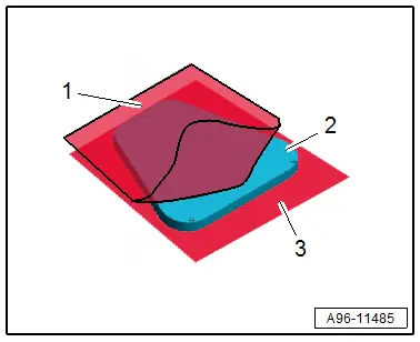
- Position the silicone pad -2- on the front camera -3- using the clear protective film -1-.
- Press the silicone pad through the protective film onto the front camera free of bubbles.
- Remove the protective film -2- from the silicone pad -1-.
TIP
To avoid contaminating the silicone pad, remove the protective film just before installing it.
- Spray the entire surface of the silicone pad with Cleaning Solution -D 009 401 04-.
- Connect the connector.
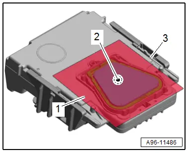
- Insert the front camera -2- in the mount -1--arrows A-.
- Push the front camera using light force onto the mount -arrow B-.
TIP
If not all bubbles are removed then pressing on the silicone pad, the bubbles will be pushed out on the windshield when locking the front camera due to contact pressure.
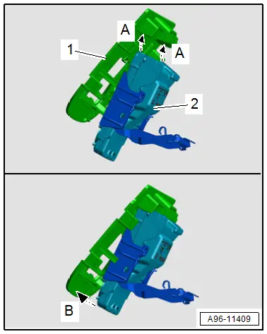
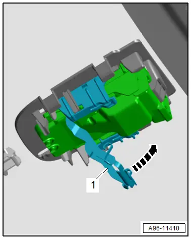
- Push the securing clip -1- in the direction of -arrow-.
- To prevent a malfunction of the assistance systems, the driver assistance systems front camera must not have any embedded objects or bubbles between it and the windshield.
- Calibrate the driver assistance systems front camera. Refer to → Suspension, Wheels, Steering; Rep. Gr.44; Driver Assistance Systems Front Camera; Driver Assistance Systems Front Camera, Calibrating.
Driver Assistance Systems Front Camera, Replacing
Special tools and workshop equipment required
- Cleaning Solution -D 009 401 04-
TIP
If replacing the control module, select the "Replace control module" function for the corresponding control module on the Vehicle Diagnostic Tester.
Removing
- Unclip the cover -1- in direction of -A, B and C arrows- with the Angled Screwdriver -VAS6416- to do so carefully guide a long reach special wrench for the flat-head screws between the windshield and the cover.
- Repeat the procedure on the opposite side.
- Disengage the front cover and remove toward the rear.
- Free up the wire if necessary.

- Release the securing clip -3- in direction of -arrow- and remove the driver assistance systems front camera -2- from the mount -1-.
- Disconnect the connector.
- Clean the adhesive surface on the windshield with Cleaning Solution -D 009 401 04-.
- Any silicone residue must be completely removed.

Installing
Install in the reverse order of removal while noting the following:
- Release the catch and remove the protective cap -3- from the front camera -2-.
TIP
To avoid contaminating the silicone pad, remove the protective cap just before installing it.
- Spray the entire surface of the silicone pad -1- with Cleaning Solution -D 009 401 04-.
- Connect the connector.
- Insert the front camera -2- in the mount -1- in direction of -arrows A-.
- Push the front camera using light force onto the mount in direction of -arrow B-.
TIP
If not all bubbles are removed then pressing on the silicone pad, the bubbles will be pushed out on the windshield when locking the front camera due to contact pressure.

- Push the securing clip -1- in the direction of -arrow-.
- To prevent a malfunction of the assistance systems, the driver assistance systems front camera must not have any embedded objects or bubbles between it and the windshield.
- Calibrate the driver assistance systems front camera. Refer to → Suspension, Wheels, Steering; Rep. Gr.44; Driver Assistance Systems Front Camera; Driver Assistance Systems Front Camera, Calibrating.

Trailer Hitch
Overview - Towing Recognition
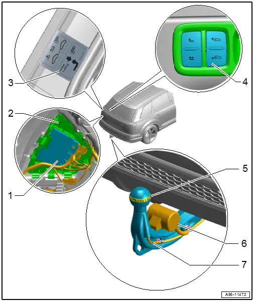
1 - Towing Recognition Control Module -J345-
- Removing and installing. Refer to → Body Exterior; Rep. Gr.66; Trailer Hitch.
2 - Frame
- For Towing Recognition Control Module -J345-
3 - Information Label
- On the body on the left rear
4 - Power Pivoting Trailer Hitch Button -E474-
- Removing and installing. Refer to → Chapter "Loading Sill Lowering Control Head -E682-/Power Pivoting Trailer Hitch Button -E474-, Removing and Installing".
5 - Trailer Hitch Bend Angle Sensor -G820-
- Removing and installing. Refer to → Body Exterior; Rep. Gr.66; Trailer Hitch; Overview - Trailer Hitch.
6 - Trailer Socket -U10-
- Removing and installing. Refer to → Electrical Equipment General Information; Rep. Gr.96; Trailer Hitch.
7 - Connector
Trailer Socket
- Refer to → Electrical Equipment General Information; Rep. Gr.96; Trailer Hitch.
Special Tools
Special tools and workshop equipment required
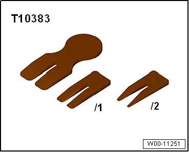
- Wedge Set -T10383-
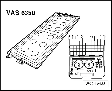
- Calibration Unit -VAS6350A-
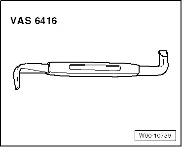
- Angled Screwdriver -VAS6416-
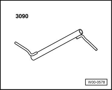
- Connecting Rod Support -3090-
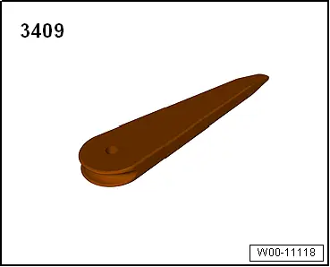
- Trim Removal Wedge -3409-
- Cleaning Solution -D 009 401 04-