Audi Q7: Component Location Overview - Relay Panels, Fuse Panels and E-Boxes
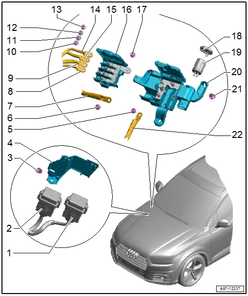
1 - Relay and Fuse Panel 1 -SR1-
2 - Relay and Fuse Panel 2 -SR2-
3 - Nut
- 3 Nm
4 - Mount
- For relay and fuse panel
5 - Nut
- 16 Nm
6 - Nut
- 16 Nm
7 - Positive Cable
- From the battery
8 - Wire
- Allocation. Refer to → Wiring diagrams, Troubleshooting & Component locations.
9 - Wire
- Allocation. Refer to → Wiring diagrams, Troubleshooting & Component locations.
10 - Nut
- 9 Nm
11 - Nut
- 9 Nm
12 - Nut
- 9 Nm
13 - Nut
- 9 Nm
14 - Wire
- Allocation. Refer to → Wiring diagrams, Troubleshooting & Component locations.
15 - Wire
- Allocation. Refer to → Wiring diagrams, Troubleshooting & Component locations.
16 - Terminal 30 Wire Junction 2 -TV22-
- Removing and installing. Refer to → Chapter "Terminal 30 Wire Junction 2 -TV22-".
17 - Nut
- 7.5 Nm
18 - Cover
19 - Suppressor -C24-
- Overview. Refer to → Chapter "Suppressor -C24-, Removing and Installing".
20 - Terminal 30 Wire Junction -TV2-
- Removing and installing. Refer to → Chapter "Terminal 30 Wire Junction -TV2-, Removing and Installing".
21 - Nut
- 3 Nm
- Quantity: 3
22 - Positive Cable
- To starter, generator
Overview - Component Location Relay Panel, Fuse Panel, E-Boxes, Left Footwell
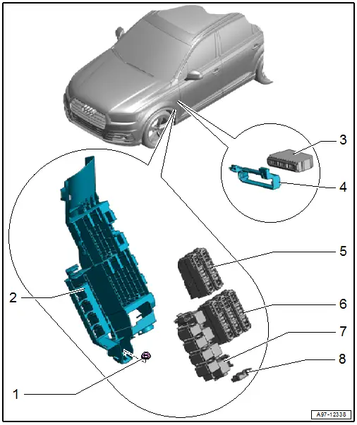
1 - Nut
- 3 Nm
- Quantity: 3
2 - Fuse Panel B -SB-
- Removing and installing. Refer to → Chapter "Fuse Panel B -SB-, Removing and Installing".
3 - Fuse Panel C -SC-
- Removing and installing. Refer to → Chapter "Fuse Panel C -SC-, Removing and Installing".
4 - Mount
- For the fuse panel C
- Removing and installing. Refer to → Chapter "Fuse Panel C -SC-, Removing and Installing".
5 - Upper Fuse Panel
- Allocation. Refer to → Wiring diagrams, Troubleshooting & Component locations.
6 - Lower Fuse Panel
- Allocation. Refer to → Wiring diagrams, Troubleshooting & Component locations.
7 - Relay Mount
- Allocation. Refer to → Wiring diagrams, Troubleshooting & Component locations.
8 - Auxiliary Fuse Panel
Overview - Component Location Relay Panel, Fuse Panel, E-Boxes, Right Footwell
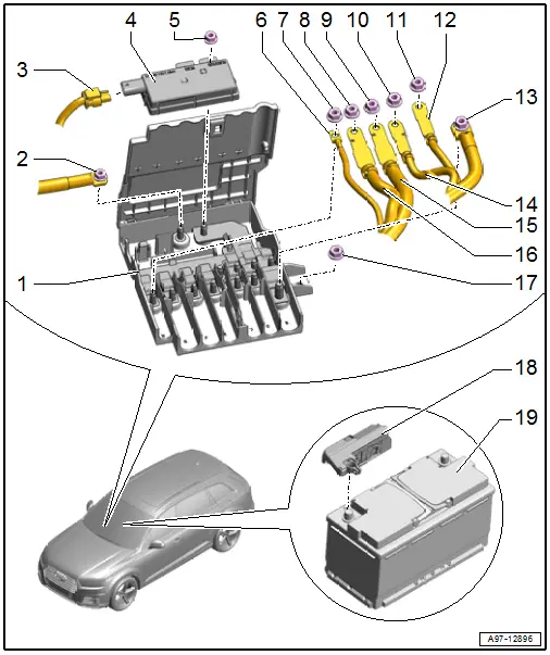
1 - Wire Junction
- Vehicles without a high-voltage system: Wire Junction -TV1-
- Vehicles with high-voltage system: Terminal 30 Wire Junction 3 -TV28-
- Removing and installing. Refer to → Chapter "Wire Junction, Removing and Installing".
2 - Positive Cable
- From the battery
- Tightening specification 9 Nm.
3 - Connector
4 - Protective Diode -J201-
- Only vehicles with high-voltage system
- Removing and installing. Refer to → Chapter "Protective Diode -J201-, Removing and Installing".
5 - Nut
- 9 Nm
6 - Line
- Allocation. Refer to → Wiring diagrams, Troubleshooting & Component locations.
7 - Nut
- 9 Nm
8 - Nut
- 9 Nm
9 - Nut
- 9 Nm
10 - Nut
- 9 Nm
11 - Nut
- 9 Nm
12 - Line
- Allocation. Refer to → Wiring diagrams, Troubleshooting & Component locations.
13 - Line
- Allocation. Refer to → Wiring diagrams, Troubleshooting & Component locations.
- Tightening specification 20 Nm
14 - Line
- Allocation. Refer to → Wiring diagrams, Troubleshooting & Component locations.
15 - Line
- Allocation. Refer to → Wiring diagrams, Troubleshooting & Component locations.
16 - Line
- Allocation. Refer to → Wiring diagrams, Troubleshooting & Component locations.
17 - Nut
- 3 Nm
- Quantity: 2
18 - Main Fuse Panel
- Tightening specifications of the wires. Refer to → Fig. "Tightening Specification for the Main Fuse Panel".
- Removing and installing. Refer to → Chapter "Main Fuse Panel on Battery, Removing and Installing".
19 - Battery
Tightening Specification for the Main Fuse Panel
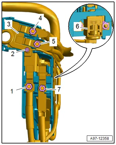
1 - Nut - 9 Nm
2 - Screw - 3.5 Nm
3 - Main Fuse Panel to Battery
4 - Nut - 9 Nm
5 - Nut - 9 Nm
6 - Battery Interrupt Igniter -N253-
7 - Wire - 9 Nm
Overview - Component Location Relay Panel, Instrument Panel, E-Boxes, Luggage Compartment
Vehicles without High-Voltage System
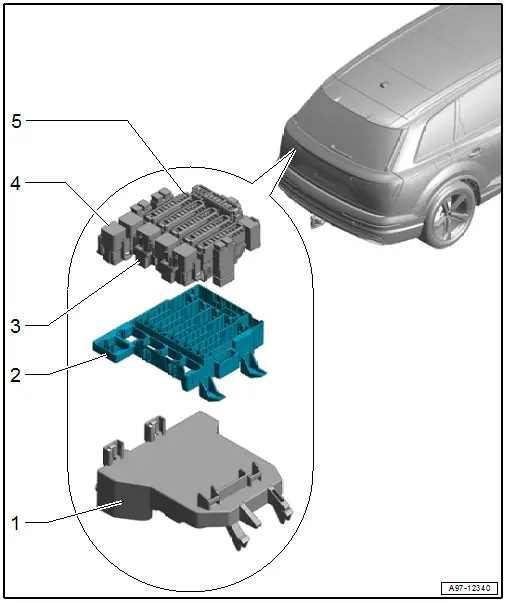
1 - Mount
- For the relay and fuse panel
2 - Relay and Fuse Panel F -SF-
- Removing and installing. Refer to → Chapter "Fuse Panel F -SF-, Removing and Installing".
3 - Auxiliary Fuse Panel
4 - Relay Mount
- Allocation. Refer to → Wiring diagrams, Troubleshooting & Component locations.
5 - Fuse Panel
- Allocation. Refer to → Wiring diagrams, Troubleshooting & Component locations.
Vehicles with High-Voltage System
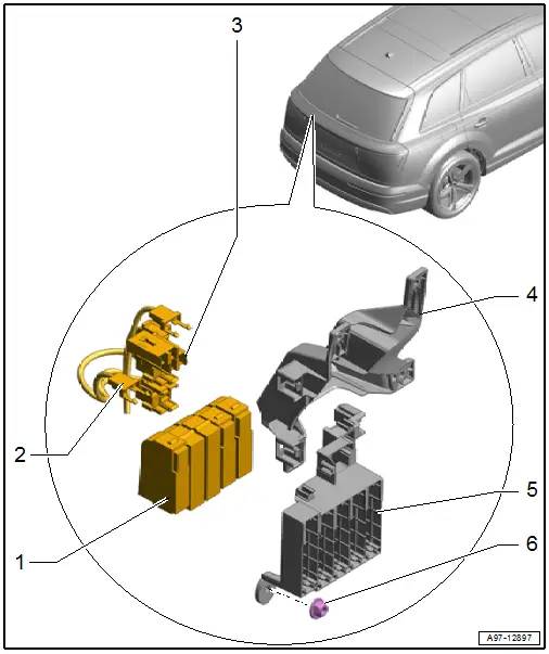
1 - Fuse Panel
- Allocation. Refer to → Wiring diagrams, Troubleshooting & Component locations.
2 - Auxiliary Fuse Panel
3 - Relay Mount
- Allocation. Refer to → Wiring diagrams, Troubleshooting & Component locations.
4 - Mount
- For the High-Voltage Battery Charging Socket 1 -UX4-
5 - Relay and Fuse Panel F -SF-
- Removing and Installing. Refer to → Chapter "Fuse Panel F -SF-, Removing and Installing".
6 - Nut
- 3.5 Nm

