Audi Q7: Malfunction Determination if Cooling Output of Front A/C System is OK but Required Values not Achieved in Rear
 Note
Note
Depending on vehicle equipment, there are different versions of the A/C system for the Audi Q7. Make sure to use the correct version and pay attention to the allocation of different components. Refer to → Chapter "A/C System Versions" and Parts Catalog.
Perform only on vehicles with a rear heater and A/C unit (vehicles with a "High" A/C system).
 Note
Note
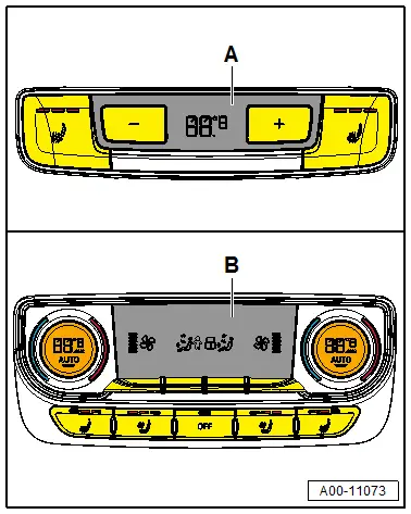
- Vehicles with a "High" A/C system can be identified by the Rear A/C Display Control Head -E265- with the Version -B-.
- Not performed on vehicles with a "Low"Mid" or "Mix" A/C system.
Requirement for this test:
- The front A/C cooling output was checked and is ok. Refer to → Chapter "Cooling Output, Checking".
When testing the cooling output, it is helpful to display the following measured values of the Rear A/C Display Control Head -E265-:
- The measured values of the following temperature sensors (Left Rear Upper Body Vent Temperature Sensor -G635-Right Rear Upper Body Vent Temperature Sensor -G636-, Left Rear Footwell Vent Temperature Sensor -G637- and Right Rear Footwell Vent Temperature Sensor -G638-).
- Open the vents in the left and right B-pillars.
- Ensure that the air outlet from the rear footwell vents (under the front seats) is not blocked by the floor mats or other objects.
- Set the air distribution on the Rear A/C Display Control Head -E265- so that the air is routed to all vents.
- In the "read measured" values of the Rear A/C Display Control Head -E265- function, select the displays with the measured values for the temperature sensors: left rear upper body vent temperature sensor Left Rear Upper Body Vent Temperature Sensor -G635-, Right Rear Upper Body Vent Temperature Sensor -G636-, Left Rear Footwell Vent Temperature Sensor -G637- and the Right Rear Footwell Vent Temperature Sensor -G638-. Refer to Vehicle Diagnostic Tester in the "Guided Fault Finding" function.
- Repeat the cooling output test. Refer to → Chapter "Cooling Output, Checking".
- Use a thermometer to measure the temperature of the air from the vents in the left and right rear center console (the measured values correspond to the temperatures previously measured by the Evaporator Vent Temperature Sensor -G263- (permissible deviation + 6ºC/- 3ºC (42.8 ºF/26.6 ºF), but not less than +1ºC (33.8 ºF) ) ). Refer to → Chapter "Cooling Output, Checking".
- Pay attention to the measured values of the different temperature sensors during the cooling output test.
- Do the temperatures in the rear measured by the various temperature sensors correspond to the temperature of the air from the vents in the left and right rear center console measured by the thermometer (the permissible deviation of the displayed values from the measured values of the thermometer is less than + 9ºC/-3ºC (+48.2 ºF/26.6 ºF) )?
- A temperature of less than +1ºC (33.8 ºF) is not measured at any measurement point.

- The cooling output in the rear is OK (end of test)
- If there is a complaint due to a lack of heating output. Refer to → Chapter "A/C System Temperature Door Heat Output Activation, Checking".
- If there is a complaint due to different temperatures of the air from the rear vents (check the temperature sensors and the control motors of the rear A/C system.). Refer to Vehicle Diagnostic Tester in the "Guided Fault Finding" function.

- Are the temperatures at a measurement point or for one side too high (or too low)?
- Check the temperature sensor with the incorrect measured value. Refer to Vehicle Diagnostic Tester in the "Guided Fault Finding" function.
- Check the activation and function of the control motors installed at the rear heater and A/C unit. Refer to Vehicle Diagnostic Tester in the "Guided Fault Finding" function.
- Are the temperatures at all measurement points (or the measurement points for one side) too high?
- Clamp off both coolant hoses to the heater and A/C unit heater core, for example using Hose Clamps - Up To 40mm -3093- (refer to → Chapter "Rear Heating and A/C system, Incorporation in the Coolant Circuit, High A/C System") and repeat the cooling output test for the rear. Refer to → Chapter "Malfunction Determination if Cooling Output of Front A/C System is OK but Required Values not Achieved in Rear".
- If the measured values of the temperature sensors are OK when the coolant lines are clamped off, check the activation of the control motors -V314- and -V315-. Refer to Vehicle Diagnostic Tester in the "Guided Fault Finding" function.
- If the measured values of the temperature sensor are not OK even with the coolant lines clamped off, bring the vehicle to a workshop that has the necessary tools and where the work can be performed by qualified personnel (the refrigerant in the circuit may be insufficient or the refrigerant flow through the rear evaporator may be insufficient). Refer to → Refrigerant R134a Servicing; Rep. Gr.87; A/C System, General Information.
- Is the temperature measured with the thermometer too low (less than +1 ºC (33.8 ºF) )?
- Bring the vehicle to a workshop that has the necessary tools and where the work can be performed by qualified personnel (the refrigerant flow through the evaporator in the rear heater and A/C unit may be too high). Refer to → Refrigerant R134a Servicing; Rep. Gr.87; A/C System, General Information.

