Audi Q7: Working on Refrigerant Circuit
Work on refrigerant system should only be performed in a ventilated rooms (workshops). Ensure that there are no workshop pits, basement staircases or shafts within a five meter circumference. Extraction systems are to be switched on.
Reason
The refrigerant emerging is not only colorless and odorless, but also heavier than air and thus displaces oxygen. If refrigerant gas does escape even though all the safety precautions have been followed, there is a risk of suffocating in poorly ventilated areas and in workshop pits - even if it is not noticeable.
 Note
Note
The escaping refrigerant/air mixture should not be inhaled, but should be sucked out via an existing exhaust ventilation system.
Never weld or hard/soft solder components of a filled A/C system. This also applies to welding and soldering on the vehicle, if there is a risk that it may heat up components in the A/C system.
Reason
Exposure to heat creates considerable pressure in the system, which could cause it to burst.
Corrective Measure
Discharge refrigerant circuit. Refer to → Chapter "Refrigerant Circuit, Discharging".
 Note
Note
Damaged or leaking parts of the air conditioner are never to be repaired by welding or soldering them; they are always to be replaced.
When servicing the A/C system, all open components and line connections are to be immediately re-sealed.
Reason
Moisture will ingress into A/C system components if they are left open for a lengthy period. If this is the case, air conditioners cannot be refilled without having to replace parts of the system.
Refrigerant Circuit, Discharging
Refrigerant is never to be allowed to escape into the atmosphere, but rather it is to be extracted from the refrigerant circuit using an extractor or A/C service station. The drained refrigerant will be locally recycled or is send to an environment-recycling place to the manufacturer (different or additional laws may apply in individual companies). Bring the vehicle to a workshop that has the necessary tools and where the work can be performed accordingly by qualified personnel. Refer to → Refrigerant R134a Servicing; Rep. Gr.87; A/C System, General Information.
Reason
If refrigerant R134a is released into the environment, it enhances the greenhouse effect.
 Note
Note
- Refrigerant R134a has far less of a greenhouse effect than R12 refrigerant.
- Because refrigerant R134a does not contain chlorine atoms, the major catalyst in ozone depletion, refrigerant R-134a has no ozone depletion potential. However, depletion of the ozone layer in the upper atmosphere is only brought about by the splitting of carbon-chlorine bonds (as is the case, for example, with refrigerant R12).
Disconnect the connector from the A/C Compressor Regulator Valve -N280- or from the A/C Pressure/Temperature Sensor -G395- after draining the air conditioner.
Reason
The A/C Compressor Regulator Valve -N280- is no longer activated and the A/C compressor runs at idle. The A/C compressor is designed so that the A/C compressor components are guaranteed to be lubricated at idle by an internal oil circuit (as long as there is enough refrigerant oil in the A/C compressor).
General Repair Information
A/C Components Controlled or Activated by Other Control Modules, Electrical Tests
 Note
Note
- Different component of the A/C system are no longer directly activated by the Front A/C Display Control Head -E87-. The A/C Compressor Regulator Valve -N280-, for example, is controlled by the Vehicle Electrical System Control Module -J519-. The data is exchanged via the data bus between both control modules via the Data Bus on Board Diagnostic Interface -J533-. Refer to Vehicle Diagnostic Tester in the "Guided Fault Finding" function.
- The measured values of different components of the A/C system is no longer evaluated by the Front A/C Display Control Head -E87-. For example, the pressure signal from the High Pressure Sensor -G65- is evaluated by the Vehicle Electrical System Control Module -J519- and the measured values are transmitted via the data bus (via the Data Bus on Board Diagnostic Interface -J533-) to the Front A/C Display Control Head -E87-. Refer to Vehicle Diagnostic Tester in the "Guided Fault Finding" function and refer to → Wiring diagrams, Troubleshooting & Component locations.
- A Start/Stop System is available for certain engines for this vehicle. The stop function can be inhibited by this, depending on the setting for the Front A/C Display Control Head -E87-. If, for example, "defrost" mode is selected, the Stop function is not possible or is canceled and the engine is started as soon as this mode is selected. The same also applies if the difference between the selected specified temperature and the measured actual temperature exceeds a certain value in heating and cooling mode. Refer to Vehicle Diagnostic Tester in the "Guided Fault Finding" function.
- Certain A/C system functions can be switched on and off via the MMI (Multi Media Interface) in the "A/C system" function under the "Car"/"Vehicle" menu. The A/C system control can also be influenced via the presets in the MMI (Multi Media Interface) under the "A/C system" function in the "Car"/"Vehicle" menu. Therefore, check the preset in the MMI first in the case there is a problem with these components. Refer to Infotainment/MMI Operating Instructions.
Components Actuated by A/C System, Electrical Test
 Note
Note
- Various electrical components of the vehicle (for example, the Rear Window Defogger -Z1- and heated seats) which are not part of the A/C system are activated by the Front A/C Display Control Head -E87- (or from the Rear A/C Display Control Head -E265-). In the case of the Rear Window Defogger -Z1-, an activation request, for example, is first transmitted via the data bus to the Data Bus On Board Diagnostic Interface -J533- and then to the Comfort System Central Control Module -J393-. The Comfort System Central Control Module -J393- then activates the Rear Window Defogger -Z1- via the Rear Window Defogger Relay -J9-. Refer to → Wiring diagrams, Troubleshooting & Component locations. Perform the electrical test for these components as described in guided fault finding for the A/C system and the Comfort System Central Control Module -J393-. Refer to Vehicle Diagnostic Tester in the "Guided Fault Finding" function.
- Certain A/C system functions can be switched on and off via the MMI (Multi Media Interface) in the "A/C system" function under the "Car"/"Vehicle" menu. The A/C system control can also be influenced via the presets in the MMI (Multi Media Interface) under the "A/C system" function in the "Car"/"Vehicle" menu. Therefore, check the preset in the MMI first in the case there is a problem with these components. Refer to Infotainment/MMI Operating Instructions.
Auxiliary Heater, Testing
 Note
Note
- An auxiliary heater is currently installed in vehicles with a diesel engine. The version depends on the vehicle equipment. Refer to Audi Sales Program.
- In vehicles with a diesel engine and without a "parking heater", an Auxiliary Heater Control Module -J604- and an Auxiliary Heater Heating Element -Z35- are installed. Via the Auxiliary Heater Heating Element -Z35- the air is heated after it exits the heat exchanger in the front heater and A/C unit. Refer to → Chapter "Electrical Auxiliary Heater, Testing" and Audi Sales Program.
- Certain A/C system functions (for example auxiliary heater activation) can be switched on and off via the MMI (Multi Media Interface) under the "A/C system" function in the "car"/"vehicle" menu. The A/C system control can also be influenced via the presets in the MMI (Multi Media Interface) under the "A/C system" function in the "Car"/"Vehicle" menu. Therefore, check the preset in the MMI first in the case there is a problem with these components. Refer to Infotainment/MMI Operating Instructions.
- In vehicles with a diesel engine and a "parking heater" (an Auxiliary Heater Heating Element -Z35- can be currently not installed in these vehicles depending on the version), the parking heater assumes the function of the Auxiliary Heater Heating Element -Z35- and acts as a fuel-driven auxiliary heater. Refer to the Audi sales program. The parking heater heats the coolant while the engine is running in these vehicles.
- The function test of the activation of the Auxiliary Heater Heating Element -Z35- via the Auxiliary Heater Control Module -J604- is described in the Guided Fault Finding of the A/C system. Refer to Vehicle Diagnostic Tester in the "Guided Fault Finding" function and refer to → Chapter "Electrical Auxiliary Heater, Testing".
- The "read measured values" function of the Guided Fault Finding of the Front A/C Display Control Head -E87-, displays the fact that the auxiliary heater is switched on or why activation did not occur despite a request. Refer to Vehicle Diagnostic Tester in the "Guided Fault Finding" function.
- On vehicles with a gasoline engine currently no Auxiliary Heater Heating Element -Z35- is installed as an auxiliary heater. The parking heater installed as optional equipment is activated as an auxiliary heater depending on the vehicle version.
Dust and Pollen Filter with Activated Charcoal Insert, Element Information
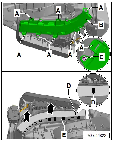
- There are different versions of dust and pollen filter -D- without and with a filter insert with activated charcoal. Refer to the Parts Catalog. A dust and pollen filter with an activated charcoal filter insert is installed in the Audi Q7.
- The activated charcoal filter element functions as a dust and pollen filter, however in addition the activated charcoal filter can also filter out gaseous pollutants, for example, ozone, benzene, nitrogen dioxide from the air flow. The basic task of the activated charcoal layer in the dust and pollen filter is to keep load peaks out of the vehicle interior.
- The activated charcoal also has the task of removing certain gaseous contaminants from the air flowing through. The activated charcoal layer in the dust and pollen filter reacts differently to various pollutants in the air:
- In the future, a dust and pollen filter with a filter element with activated charcoal and with a special anti-allergen effect can be installed. The implementation is not yet finalized. Refer to the Parts Catalog.
- Certain pollutants bond permanently in the activated charcoal layer.
- Others are converted into innoxious bonds as in a catalytic converter.
- For the rest the activated charcoal works as a condenser (capacitor). With increasing load pollutants are absorbed, until a certain saturation is reached. If the amount of pollutants decreases, the activated charcoal layer continuously releases the absorbed particles.
- Because a portion of the gaseous pollutant particles as well as dust and pollen bond permanently to the activated charcoal layer, the dust and pollen filter should be changed more often than scheduled under the following conditions:
- If vehicle is driven in areas with constant strong air pollution. the activated charcoal layer in the dust and pollen filter is saturated faster than planned.
- If vehicle is predominantly driven with the "automatic recirculating air mode" switched off.
t If possible, vehicles with A/C system with one Air Quality Sensor -G238- should always be operated in "automatic air recirculation" mode. However, if it is desired or necessary to switch this mode off, the following must be observed:
- Activated charcoal layer in dust and pollen filter becomes saturated after a certain time.
- A saturated filter can no longer absorb pollutants and allows them to pass unhindered.
- The most important task of the dust and pollen filter activated charcoal filter element and the Air Quality Sensor -G238- is keep the load peaks out from the passenger compartment. For this the following must be observed:
- If the vehicle is driven in an area with relatively clean air with few air pollutants. The switch-over from fresh air mode to recirculating air mode will occur at a different time than on a vehicle driven in an area that has high air pollutants, for example, in an industrial area.
- Independently of the basic load, the change-over from fresh to recirculating mode always occurs, when the pollutant-load increases (for example, when driving to through an exhaust cloud of a diesel truck).
Painting on Vehicles with A/C System
When performing paint work repairs, object temperatures of 80 ºC (176 ºF) are must not be exceeded in drying booths or their pre-heating areas.
Reason
Exposure to heat creates considerable pressure in the system, which could cause it to burst.
Refrigerant Circuit Seals
- Always use O-rings only once, replace.
- Coat the O-rings with refrigerant oil before installing.
- Make sure O-rings are seated properly on pipe or in groove.
- Check the connections on the components and refrigerant lines for damage (even a small scratch can lead to leakage).
- Perform the work under clean conditions (even the smallest deposit such as a hair may cause a leak).
 Note
Note
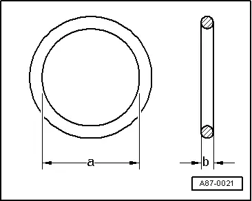
- Only install O-rings that are resistant to refrigerant R134a and the associated refrigerant oil. These O-rings are color-coded to avoid confusion (currently "red", "light purple" or "dark purple"). Refer to the Parts Catalog.
- The dimensions -a and b- are different depending on the component location of the O-ring. Refer to the Parts Catalog.
- In addition to the color-coded O-rings, black O-rings are also installed at the factory for certain connections.