Audi Q7: Overview - Front Brakes
Audi Q7 (4M) 2016-2025 Workshop Manual / Chassis / Brake System / Mechanical Components / Overview - Front Brakes
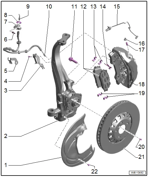
1 - Brake Shield
- Refer to → Chapter "Brake Shield, Removing and Installing"
2 - Wheel Bearing Housing
3 - Bracket
- For brake hose
4 - Bolt
- 20 Nm
5 - Bracket
- For brake hose
6 - Rivet
7 - Bracket
- For the brake line/hose
- On the body
8 - Spring
- Replace if damaged
9 - Brake Line
- Tightening specification, brake line to brake hose, 14 Nm
10 - Brake Hose
- Tightening specification: brake hose to brake caliper, 14 Nm
- Allocation. Refer to the Parts Catalog.
- Make sure the brake hose is routed correctly. Make sure the brake hose is not blocked, bent, twisted or rubbing against the vehicle.
- Replace if damaged
- Make sure that lugs are properly seated in grooves in bracket.
11 - Bolt
- 196 Nm
- Replace after removing
12 - Brake Pads
- Checking pad thickness. Refer to → for the wear limit.
- Always replace on both axles.
- Allocation. Refer to the Parts Catalog.
- Refer to → Chapter "Brake Pads, Removing and Installing"
- Installation position. Refer to → Fig. "Brake Pads Installation Position".
13 - Brake Pad Retaining Plate
- Replace when pads are replaced.
- Check for proper seating
14 - Brake Pad Spring
- Replace when pads are replaced.
- Check for proper seating
15 - Brake Pad Wear Indicator Wire
- With
- Left Front Brake Pad Wear Sensor -G34-
- Right Front Brake Pad Wear Sensor -G35-
- For inner brake pad
- Replace when replacing the brake pads.
- Refer to → Chapter "Brake Pad Wear Indicator Wire, Removing and Installing"
16 - Protective Cap
17 - Bleed Screw
- 10 Nm
- Before installing, thinly coat with Assembly Paste -G 052 150 A2-.
18 - Brake Caliper
- Allocation. Refer to the Parts Catalog.
- Do not loosen the brake caliper/brake carrier bolted connections. Refer to → Fig. "Do Not Loosen the Caliper/Brake Carrier Bolted Connections.".
- Refer to → Chapter "Brake Caliper, Removing and Installing"
- Refer to → Chapter "Brake Caliper, Replacing"
- Refer to → Chapter "Dust Cap, Removing and Installing"
19 - Brake Pad Retaining Plate
- Replace when pads are replaced.
- Check for proper seating
20 - Bolt
- 10 Nm
21 - Brake Rotor
- Allocation. Refer to the Parts Catalog.
- Always replace on both axles.
- Do not use excessive force to separate the brake rotors from the wheel hub. Use rust remover, if necessary, otherwise the brake rotors could be damaged.
- Refer to → Chapter "Brake Rotor, Removing and Installing"
22 - Bolt
- 10 Nm
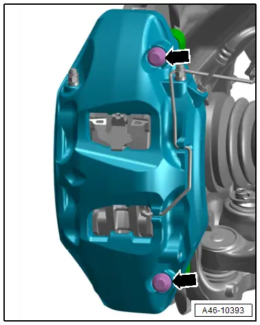
Do Not Loosen the Caliper/Brake Carrier Bolted Connections.
 Caution
There is a risk of malfunctions.
Do not loosen the bolts -arrows- on the brake caliper.
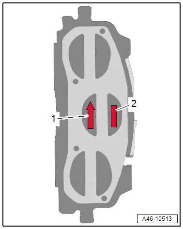
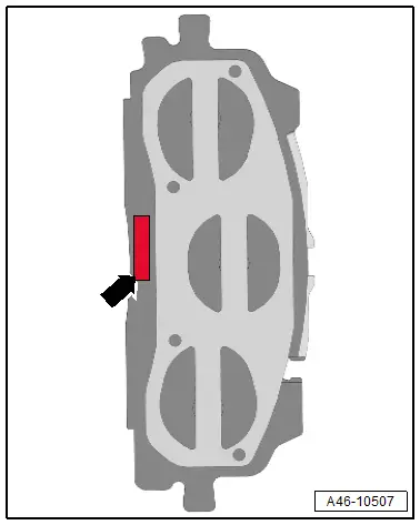
Brake Pads Installation Position
Version 1:
- Pay attention to the labeling -arrow- on the brake pads.
- LEFT OUTER
- LEFT INNER
- RIGHT OUTER
- RIGHT INNER
Version 2:
- Pay attention to the labeling -2- on the brake pads.
- LEFT OUTER
- LEFT INNER
- RIGHT OUTER
- RIGHT INNER
- In installed position, the arrow -1- on the backing plate of the brake pads must point upward.