Audi Q7: Overview - Lock Carrier
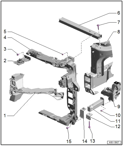
1 - Mount
- For headlamp.
- Removing and installing. Refer to → Electrical Equipment; Rep. Gr.94; Headlamps Removing and Installing.
2 - Mounting Bracket with Release Cable
- For the hook release lever
- Overview. Refer to → Chapter "Overview - Release on Latch".
3 - Bolt
- Quantity: 2
- Tightening specification. Refer to → Chapter "Overview - Release on Latch".
4 - Lock Carrier
- There are different versions. Refer to the Parts Catalog.
- Removing and Installing. Refer to → Chapter "Lock Carrier, Removing and Installing".
5 - Bolt
- 8 Nm
6 - Reinforcement Brace
- Removing and Installing. Refer to → Chapter "Reinforcement Brace, Removing and Installing".
7 - Bolt
- 10 Nm
- Quantity: 2
8 - Body
9 - Subframe
10 - Bolt
- 10 Nm
- Quantity: 4
11 - Lower Longitudinal Member
- Removing and Installing. Refer to → Chapter "Lower Longitudinal Member, Removing and Installing".
12 - Bracket
- For the lower longitudinal member
- Removing and Installing. Refer to → Chapter "Lower Longitudinal Member Bracket, Removing and Installing".
13 - Bolt
- 25 Nm
14 - Bracket
- For the lower longitudinal member
- Removing and Installing. Refer to → Chapter "Lower Longitudinal Member Bracket, Removing and Installing".
15 - Bolt
- 23 Nm
- Quantity: 2
Lock Carrier, Removing and Installing
- To complete the procedure, a second technician is required to be at the following position.
Special tools and workshop equipment required
- Coolant Collecting System -VAS5014-
- Engine Bung Set -VAS6122-
- Elbow Assembly Tool -T10118-
Removing
- Remove the impact member. Refer to → Chapter "Impact Member, Removing and Installing".
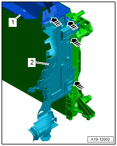
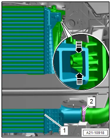
- Release the left and right catches with the -T10118--arrows- and lift the upper air duct -1- slightly and remove and side air duct -2-.
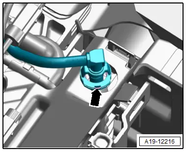
- Disconnect the connector -2- for the High Pressure Sensor -G65-.
 Caution
Risk of destroying the refrigerant lines by tearing the inner film.
- Never bend refrigerant lines with a radius less than 100 mm.
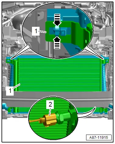
- Release the left and right catches -arrows- disengage the condenser -1- from the radiator and tie up to the side.
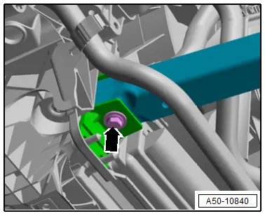
- Remove the bolt -arrow-.
- Place the container of the Coolant Collection System -VAS5014- or the -VAS6208- underneath.
- Lift the clamp -arrow- and remove the coolant hose from the lower right of the radiator and drain the coolant.
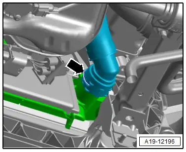
- Equipped on some models: lift up the clamp -arrow- and remove the coolant hose from the lower left side of the radiator and drain the coolant.
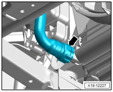
- Equipped on some models: lift up the clip -arrow- and remove the coolant line from the charge air cooling circuit cooler.
- Remove the coolant hoses from the coolers.
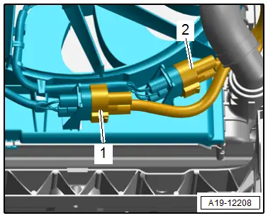
- Disconnect the connectors -1 and 2- for the radiator fan.
Vehicles with a TDI Engine:
- Vehicles with center charge air cooler: loosen the hose clamp -2-, and remove the air duct hose from the center charge air cooler -1-.
- Seal the open lines and connections with clean plugs from the -VAS6122-.
- Vehicles with side charge air cooler: remove the side charge air cooler. Refer to → Engine Mechanical; Rep. Gr.21; Charge Air System; Charge Air Cooler, Removing and Installing.
Continuation for All Vehicles:
- Free up the hoses and wires.
- Disconnect the latch cable at the coupling and free it up on the lock carrier. Refer to → Chapter "Overview - Release Cable".
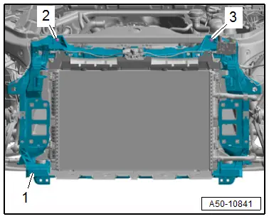
- Have a second technician hold the lock carrier -1- and remove the bolts -2 and 3-.
- Remove the lock carrier with a second technician.
- The following components must also be removed if the lock carrier is being replaced:
- Front upper air duct pipe on the lock carrier. Refer to → Engine Mechanical; Rep. Gr.21; Charge Air System; Overview - Charge Air System.
- Radiator. Refer to → Engine Mechanical; Rep. Gr.19; Radiator/Radiator Fan; Radiator, Removing and Installing.
- Latch. Refer to → Chapter "Latch, Removing and Installing".
- Bracket for the lower longitudinal member. Refer to → Chapter "Lower Longitudinal Member Bracket, Removing and Installing".
Installing
Install in reverse order of removal and note the following:
- Fill the coolant. Refer to → Engine Mechanical; Rep. Gr.19; Cooling System/Coolant; Coolant, Draining and Filling.
Tightening Specifications
- Refer to → Chapter "Overview - Lock Carrier"

