Audi Q7: Overview - Pneumatic System
Overview - Pneumatic System, Compressor
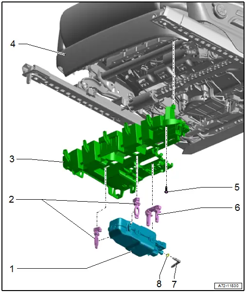
1 - Driver Multi-Contour Seat Compressor -V439- with integrated Driver Multi-Contour Seat Control Module -J873-
- Front passenger side: Front Passenger Multi-Contour Seat Compressor -V440- with integrated Front Passenger Multi-Contour Seat Control Module -J872-
- Removing and installing. Refer to → Chapter "Pneumatic Seat Compressor, Removing and Installing".
2 - Rubber Bracket
- For the supercharger
- Quantity: 2
3 - Bracket
- For seat trim at the front
- Removing and installing. Refer to → Chapter "Front Seat Trim Bracket, Removing and Installing".
4 - Front Seat
5 - Bolt
- Quantity: 2
- Tightening specification. Refer to -item 1-
6 - Rubber Bracket
- For the supercharger
7 - Angle Piece for Pneumatic Line
8 - O-Ring
- Replace after removing
Overview - Pneumatic System, Massage Mat
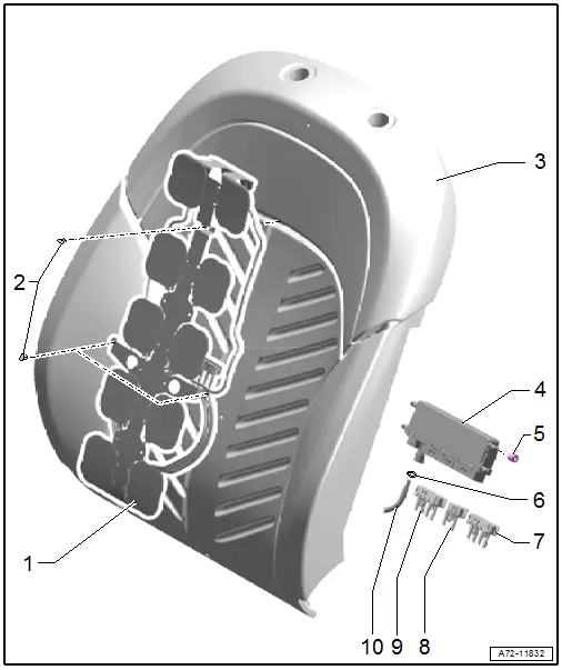
1 - Massage Mat
- Removing and installing. Refer to → Chapter "Massage Mat, Removing and Installing".
- Press in the pneumatic lines until they audibly engage
- Pull to check whether the coupling is locked in correctly
2 - Clips
- To secure the massage mat
- Quantity: 3
- Replacing
3 - Cushion
- Removing and installing. Refer to → Chapter "Backrest Cover and Cushion, Separating".
4 - Valve Block 2 in Driver Seat -N476-
- Front passenger side: Valve Block 2 in Front Passenger Seat -N478-
- For massage mat
- Removing and installing. Refer to → Chapter "Valve Block 2 in Driver Seat -N476-/ Valve Block 2 in Front Passenger Seat -N478-, Removing and Installing".
- Connect the pneumatic lines. Refer to → Chapter "Pneumatic Lines, Disconnecting and Connecting"
5 - Rubber Buffer
- Valve block mount
- Quantity: 4
6 - O-Ring
- Replace after removing
7 - Hose Connector Coupling
- 4-pin
8 - Hose Connector Coupling
- 2-pin
9 - Hose Connector Coupling
- 4-pin
10 - Pneumatic Line
Overview - Pneumatic System, Module Carrier/Lumbar Support/Seat Bolster Adjuster
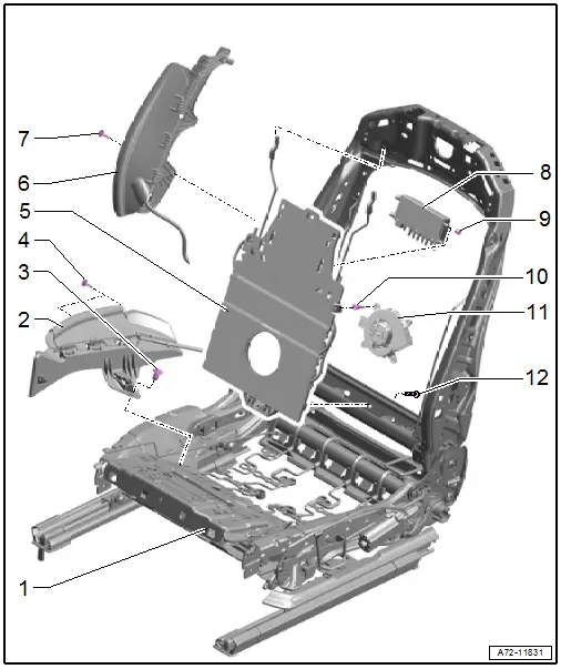
1 - Seat Frame
2 - Seat bolster inflation adjustment
- Quantity: 2
- Removing and installing. Refer to → Chapter "Seat Bolster Adjuster Air Cushion, Removing and Installing".
3 - Expanding Clip
4 - Bolt
- 2.5 Nm
5 - Module Carrier
- Module carrier with air cushions for lumbar support
- Removing and installing. Refer to → Chapter "Valve Block 1 in Driver Seat -N475-/ Valve Block 1 in Front Passenger Seat -N477- and Air Cushions, Removing and Installing".
6 - Backrest Bolster Inflation Adjuster
- Quantity: 2
- Removing and installing. Refer to → Chapter "Valve Block 1 in Driver Seat -N475-/ Valve Block 1 in Front Passenger Seat -N477- and Air Cushions, Removing and Installing".
7 - Bolt
- 2.5 Nm
8 - Valve Block 1 in Driver Seat -N475-
- Front passenger side: Valve Block 1 in Front Passenger Seat -N477-
- Removing and installing. Refer to → Chapter "Valve Block 1 in Driver Seat -N475-/ Valve Block 1 in Front Passenger Seat -N477- and Air Cushions, Removing and Installing".
9 - Rubber Buffer
- Quantity: 4
10 - Rubber Bracket
- For blower fan
- Quantity: 4
11 - Driver Seat Backrest Blower Fan -V388-
- Front passenger side: Front Passenger Seat Backrest Blower Fan -V389-
- Removing and installing. Refer to → Chapter "Backrest Fan, Removing and Installing".
12 - Bolt
- 6.5 Nm

