Audi Q7: Rear Brake Rotor, Removing and Installing
Special tools and workshop equipment required
- Torque Wrench 1410 -VAG1410-
Removing
- Remove the brake caliper. Refer to → Chapter "Brake Caliper, Removing and Installing".
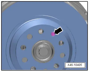
- Remove the bolt -arrow- and remove the brake rotor.

 Caution
Risk of damaging the brake rotors.
Do not separate the brake rotor from the wheel hub by force. If required, use rust remover.
Installing
Install in reverse order of removal and note the following:
- Before reusing brake rotors check for wear and damage.
- Brake rotor wear limit. Refer to → Chapter "Technical Data".
 Note
Note
- Always replace brake rotors on both sides of the axle.
- Brake pads likewise must be replaced on both sides of the axle.
- Thoroughly clean the brake rotor and hub contact surfaces and free them of corrosion.
- Do not tilt the brake rotor when mounting it on the wheel hub.
- Tighten the bolt -arrow-.
- Install the brake caliper. Refer to → Chapter "Brake Caliper, Removing and Installing".
 WARNING
Risk of accident!
- With the vehicle stationary, firmly press the brake pedal several times so that the brake pads in the operating condition properly set in their respective position.
- Make sure the brakes are working correctly before driving the vehicle for the first time.
Tightening Specifications
- Refer to → Chapter "Overview - Rear Brakes"
Rear Brake Shield, Removing and Installing
Removing
- Remove the brake rotor. Refer to → Chapter "Brake Rotor, Removing and Installing".
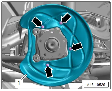
- Remove the bolts -arrows- and remove the brake shield -1-.
Installing
Install in reverse order of removal and note the following:
- Clean the contact surfaces on the brake shield and wheel hub.
- Install the brake rotor. Refer to → Chapter "Brake Rotor, Removing and Installing".
 WARNING
Risk of accident!
- With the vehicle stationary, firmly press the brake pedal several times so that the brake pads in the operating condition properly set in their respective position.
- Make sure the brakes are working correctly before driving the vehicle for the first time.
Tightening Specifications
- Refer to → Chapter "Overview - Rear Brakes"
Rear Brake Pad Wear Indicator Wire, Removing and Installing
Removing
- Remove the rear wheel. Refer to → Suspension, Wheels, Steering; Rep. Gr.44; Wheels and Tires.
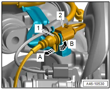
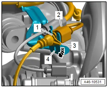
- Disconnect the connector -2- from the brake pad wear indicator contact.
- Release the connector -1- to the brake pad wear indicator contact from its bracket in direction of -arrow A- while turning it 90º at the same time in direction of -arrow B-.
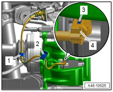
- Free up the wire, to do so open the dust protective cap -2- from the bleed screw and open the clip -1-.
- Carefully remove the contact -4- for the brake pad wear indicator using pliers at the same time pay attention to the clip -3-.

 Note
Note
If the clips go missing, the brake pad wear indicator wire must be replaced.
Installing
 Note
Note
- Check the brake pad wear indicator contact for damage and if required replace.
- Make sure that the brake pad wear indicator contact fits correctly in the brake pad.
- If the clips go missing, the brake pad wear indicator wire must be replaced.
- Insert the contact -4- for the brake pad wear indicator with the clip -3- until it engages in the inner brake pad.
- Secure the brake pad wear indicator wire with the dust protective cap -2- and the clip -1-, as shown.
- Bring the connector -1- into its installed position and turn in the direction of -arrow- until the tab -3- engages in the hole -4- on the bracket.
- Connect the connector -2-.
Tightening Specifications
- Refer to → Chapter "Overview - Rear Brakes"
- Refer to → Suspension, Wheels, Steering; Rep. Gr.44; Wheels and Tires.

