Audi Q7: Overview - Steering Column
Audi Q7 (4M) 2016-2025 Workshop Manual / Chassis / Suspension, Wheels, Steering / Steering / Overview - Steering Column
Overview - Steering Column, Manual
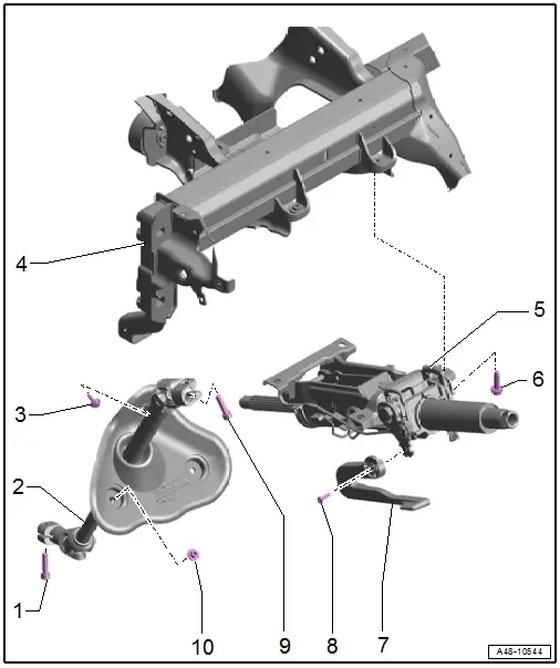
1 - Bolt
- 20 Nm +90º
- Replace after removing
- Clean the threaded hole, for example, using a thread tap, before installing the new bolt.
- Install the bolt first by hand in the first threads. Check if the steering intermediate shaft is seated correctly by pulling. Then tighten the bolt.
2 - Steering Intermediate Shaft
- Removing and installing. Refer to → Chapter "Steering Intermediate Shaft, Removing and Installing".
3 - Bolt
- 4.5 Nm
4 - Central Tube
5 - Steering Column
- Removing and installing. Refer to → Chapter "Steering Column, Removing and Installing".
- Check for damage. Refer to → Chapter "Steering Column, Checking for Damage".
6 - Bolt
- Quantity: 4
- Tightening specification and sequence. Refer to → Fig. "Steering Column - Tightening Specification and Sequence".
7 - Handle
- For manual steering column adjustment
8 - Bolt
- 5 Nm
9 - Bolt
- 20 Nm +90º
- Replace after removing
- Clean the threaded hole (for example, using a thread tap) before installing the new bolt.
- Install the bolt first by hand in the first threads. Check the if the steering intermediate shaft is seated correctly by pulling. Then tighten the bolt.
10 - Nut
- 4.5 Nm
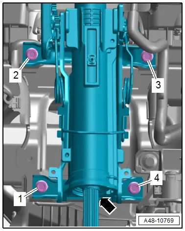
Steering Column - Tightening Specification and Sequence
- Tighten the steering column bolts -arrows- to 20 Nm in a -1 to 4- sequence.
Overview - Steering Column, Power
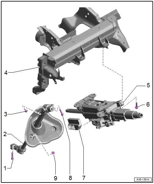
1 - Bolt
- 20 Nm +90º
- Replace after removing
- Clean the threaded hole, for example, using a thread tap, before installing the new bolt.
- Install the bolt first by hand in the first threads. Check if the steering intermediate shaft is seated correctly by pulling. Then tighten the bolt.
2 - Steering Intermediate Shaft
- Removing and installing. Refer to → Chapter "Steering Intermediate Shaft, Removing and Installing".
3 - Bolt
- 4.5 Nm
4 - Central Tube
5 - Steering Column
- Removing and installing. Refer to → Chapter "Steering Column, Removing and Installing".
- Check for damage. Refer to → Chapter "Steering Column, Checking for Damage".
6 - Bolt
- Quantity: 4
- Tightening specification and sequence. Refer to → Fig. "Steering Column - Tightening Specification and Sequence".
7 - Power Adjustable Steering Column Control Module -J866-
- Removing and installing. Refer to → Chapter "Power Adjustable Steering Column Control Module -J866-, Removing and Installing".
8 - Bolt
- 20 Nm +90º
- Replace after removing
- Clean the threaded hole, for example, using a thread tap, before installing the new bolt.
- Install the bolt first by hand in the first threads. Check if the steering intermediate shaft is seated correctly by pulling. Then tighten the bolt.
9 - Nut
- 4.5 Nm

