Audi Q7: Brake Pedal
Overview - Brake Pedal
 WARNING
Risk of accident!
The path of the brake pedal must not be shortened by extra floor mats.
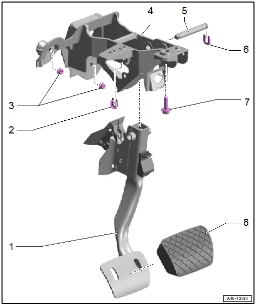
1 - Brake Pedal
- Refer to → Chapter "Brake Pedal, Disconnecting from Brake Booster"
- Refer to → Chapter "Brake Pedal, Attaching to Brake Booster"
- Refer to → Chapter "Brake Pedal, Removing and Installing"
2 - Clip
- Replace after removing
3 - Nuts
- 8 Nm
4 - Mounting Bracket
- For foot pedal assembly
- Refer to → Chapter "Mounting Bracket, Removing and Installing"
5 - Mounting Pin
- For brake pedal
6 - Clip
- Replace after removing
7 - Bolt
- 20 Nm
- Pedal bracket to steering column
8 - Pedal Rubber
Mounting Bracket, Removing and Installing
Special tools and workshop equipment required
- Torque Wrench 1410 -VAG1410-
- Torque Wrench 1331 5-50Nm -VAG1331-
Removing
- Remove the plenum chamber cover. Refer to → Body Exterior; Rep. Gr.50; Bulkhead; Plenum Chamber Cover, Removing and Installing.
- Disconnect the brake pedal from the brake booster. Refer to → Chapter "Brake Pedal, Disconnecting from Brake Booster".
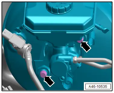
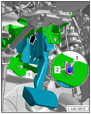
- Remove the bolts -arrows-.
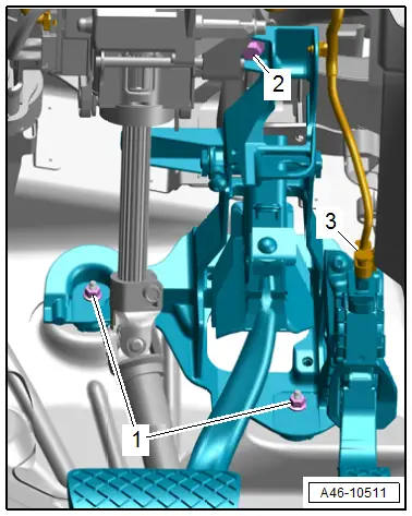
- Disconnect the connector -3- and free up the wire.
- Remove the nuts -1- and bolt -2-, then remove the mounting bracket with the brake pedal and accelerator pedal module installed.
- Remove the brake pedal. Refer to → Chapter "Brake Pedal, Removing and Installing".
- Remove the accelerator pedal module. Refer to → Rep. Gr.20; Accelerator Mechanism; Accelerator Pedal Position Sensors G79/G185, Removing and Installing
Installing
Install in reverse order of removal and note the following:
- Install the accelerator pedal module. Refer to → Rep. Gr.20; Accelerator Mechanism; Accelerator Pedal Position Sensors G79/G185, Removing and Installing
- Install the brake pedal. Refer to → Chapter "Brake Pedal, Removing and Installing".
- Bring the mounting bracket with the installed brake pedal and accelerator pedal module into the installation position.
- The mounting bracket must be seated in the bulkhead guide and all stud bolts.
- Connect the brake pedal to the brake booster. Refer to → Chapter "Brake Pedal, Disconnecting from Brake Booster".
 WARNING
Risk of accident!
Make sure the brakes are working correctly before driving the vehicle for the first time.
Tightening Specifications
- Refer to → Chapter "Overview - Brake Pedal"
- Refer to → Chapter "Overview - Brake Booster/Brake Master Cylinder"
Brake Pedal, Disconnecting from Brake Booster
Special tools and workshop equipment required
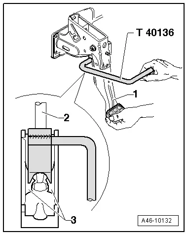
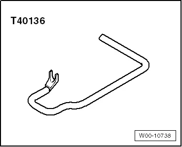
- Brake Servo Release Tool -T40136-
Procedure
- Remove the footwell vent. Refer to → Heating, Ventilation and Air Conditioning; Rep. Gr.87; Air Duct; Driver Side Footwell Vent, Removing and Installing.
- Press and hold the brake pedal in the direction of the brake booster.
- Insert the Brake Servo Release Tool -T40136- and pull in the direction of the driver seat while counterholding at the brake pedal -1- so that it does not move backward. While doing so, the retaining tabs -3- will be pushed out of the pushrod ball head mount -2-.
 Note
Note
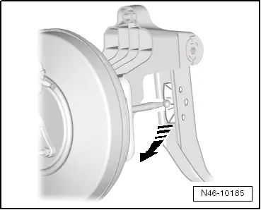
For clarity, the installation position is shown with the pedal assembly removed.
- Pull the Brake Servo Release Tool -T40136- and the brake pedal together toward the driver seat. This will pull the brake pedal off the push rod ball head.
Brake Pedal, Attaching to Brake Booster
Procedure
- Hold the pushrod ball head in front of the mount and push the brake pedal toward the brake booster in direction of -arrow- until the ball head engages audibly.
- Install the footwell vent. Refer to → Heating, Ventilation and Air Conditioning; Rep. Gr.87; Air Duct; Driver Side Footwell Vent, Removing and Installing.
 WARNING
Risk of accident!
Make sure the brakes are working correctly before driving the vehicle for the first time.
Brake Pedal, Removing and Installing
Special tools and workshop equipment required
- Torque Wrench 1410 -VAG1410-
 Caution
This procedure contains mandatory replaceable parts. Refer to component overview prior to starting procedure.
Mandatory Replacement Parts
- Clips - Mounting Pin to Mounting Bracket
Removing
- Disconnect the brake pedal from the brake booster. Refer to → Chapter "Brake Pedal, Disconnecting from Brake Booster".
- Loosen the bolt -arrow- and remove the clip -2-.
- Remove the mounting pin -3- to the left side and remove the brake pedal -1-.
Installing
Install in reverse order of removal and note the following:
- Insert the mounting pin -3- from the left all the way and secure using the clip -2- and bolt -arrow-.
- Connect the brake pedal -1- to the brake booster. Refer to → Chapter "Brake Pedal, Disconnecting from Brake Booster".

 WARNING
Risk of accident!
Make sure the brakes are working correctly before driving the vehicle for the first time.
Tightening Specifications
- Refer to → Chapter "Overview - Brake Pedal"
Special Tools
Special tools and workshop equipment required
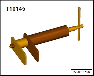
- Piston Resetting Tool -T10145-
- Brake Servo Release Tool -T40136-
- Torque Wrench 1331 5-50Nm -VAG1331-
- Torque Wrench 1332 40-200Nm -VAG1332-
- Torque Wrench 1410 -VAG1410-
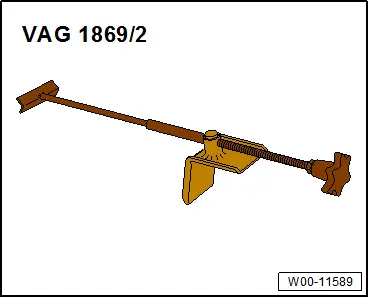
- Brake Pedal Actuator -VAG1869/2-.
- Bleeder bottle from the Brake Charger/Bleeder Unit -VAS5234-
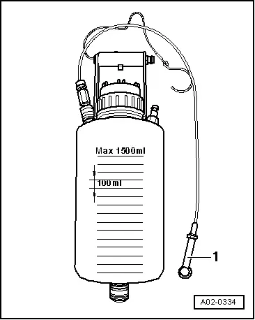
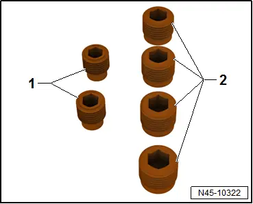
- M10 plug -item 1- or M12 -item 2- from the Assembly Part Set -5Q0 698 311-
- Lithium Grease -G 052 150 A2-. Refer to the Parts Catalog.