Audi Q7: Refrigerant Circuit Pressures and Temperatures
General Information
 Caution
When performing work on refrigerant circuit, observe all generally applicable safety precautions and pressure container regulations.
The pressures and temperatures in the refrigerant circuit depend on the current operating conditions (such as engine RPM, coolant fan level 1, 2 or 3, engine temperature, A/C compressor on or off) as well as on the effects of outside influences (such as outside temperature, humidity, desired cooling output).
In vehicles with A/C Compressor Regulator Valve -N280-, the pressure is modified on the low pressure side by the -N280-.
On vehicles with an Electrical A/C Compressor -V470- the refrigerant circuit pressure (high and low-pressure sides) is regulated via the A/C compressor speed sensor.
On vehicles with an Electrical A/C Compressor -V470- on which the A/C system does not only cool the vehicle interior but also cools the components of the high-voltage system and is used as a heat pump to heat the vehicle interior, other conditions, pressures and temperatures in the refrigerant circuit apply (for example in the Audi Q7 e-tron). Use the Vehicle Diagnostic Tester in the "Guided Fault Finding" function and refer to → Heating, Ventilation and Air Conditioning; Rep. Gr.87; Refrigerant Circuit; System Overview - Refrigerant Circuit (vehicle-specific repair manual).
For this reason, values indicated in the following table are valid only as reference points. They are attained at an engine speed of 1500 to 2000 RPM and an ambient temperature of 20 ºC (68 ºF) after approximately 20 minutes.
The connections for the pressure gauge set intended for the pressure measurement are indicated on the vehicle specific refrigerant circuit. Refer to → Heating, Ventilation and Air Conditioning; Rep. Gr.87; System Overview - Refrigerant Circuit or (vehicle-specific repair manual).
At 20 ºC (68 ºF) with the engine not running, the pressure in the refrigerant circuit is 4.7 bar (68 psi). Refer to → Chapter "Refrigerant R134a Vapor Pressure Table" (vapor pressure table).
 Note
Note
Pressure is measured in different units: 1 MPa (145 psi) corresponds to 10 bar (145 psi) positive pressure. 1 bar (14.5 psi) absolute pressure corresponds to 0 bar/psi positive pressure and thus to the ambient pressure (atmospheric pressure).
Refrigerant Circuit with Expansion Valve
 Note
Note
Applies to vehicles with an Electrical A/C Compressor -V470- only with restrictions.
HP- High pressure side of refrigerant circuit.
LP- Low pressure side of refrigerant circuit.
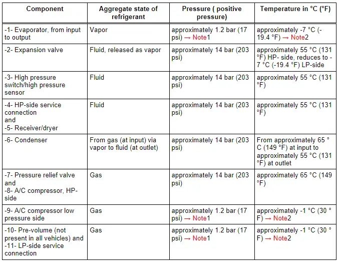
1) 1- Pressure in refrigerant circuits is maintained at approximately 2 bar (29 psi) absolute pressure (corresponds to approximately 1 bar (14.5 psi) positive pressure), regulated by A/C compressor, even though heat transfer changes and engine speeds vary. However, this applies only within the performance range of the A/C compressor; if the performance limits of the A/C compressor are exceeded, the pressure increases. Refer to → Chapter "Pressures, Checking".
2) 2 - Within the control range of the A/C compressor, temperature in the refrigerant circuits is maintained, regulated by A/C compressor, even though heat transfer changes and engine speeds vary. However, this applies only within the performance range of the A/C compressor; if the performance limits of the A/C compressor are exceeded, the temperature increases → Chapter "Pressures, Checking".
 Note
Note
- A/C compressors which do not regulate their performance are switched off by the respective control module via the A/C Compressor Regulator Valve -N280- at an evaporator temperature below 0 ºC (32 ºF).
- In vehicles with A/C Compressor Regulator Valve -N280-, the pressure is modified on the low pressure side by the valve.
- Temperature and pressure in the refrigerant circuit in vehicles with two evaporators and two expansion valves correspond to those in vehicles with only one evaporator and one expansion valve (parallel switching).
- Depending on the version of the refrigerant circuit, a component with an inner heat exchanger may be installed (for example, on the Audi A4 from MY 2008 and on the Audi A5 Coupe from MY 2008, a refrigerant line with an inner heat exchanger). Inside the inner heat exchanger, the flowing fluid warm refrigerant on the high pressure side is delivered into the low pressure side as flowing, vapor, cold refrigerant to increase the efficiency of the A/C system. Refer to → Chapter "Refrigerant Line with Inner Heat Exchanger".
Arrows point in direction of refrigerant flow.
HP- High pressure side of refrigerant circuit.
LP- Low pressure side of refrigerant circuit.
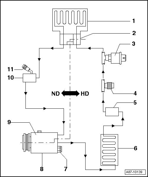
1 - Evaporator
2 - Expansion Valve
3 - High Pressure Switch/High Pressure Sensor
- Different versions depending on vehicle
4 - Service Connection, HP Side
5 - Receiver/Dryer
- Different versions depending on vehicle
6 - Condenser
7 - Pressure Relief Valve
8 - A/C Compressor, HP side
9 - A/C Compressor, LP side
10 - Pre-Volumes
- Not present on all vehicles
11 - Service Connection, LP Side
Refrigerant Circuit with Restrictor and Reservoir
HP- High pressure side of refrigerant circuit.
LP- Low pressure side of refrigerant circuit.
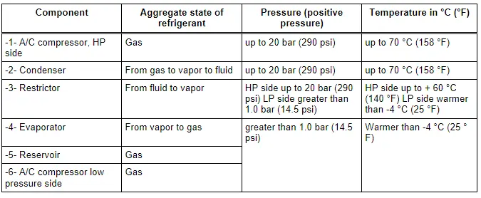
Pressures on A-side are maintained at approximately 2 bar (29 psi) absolute pressure (corresponds to approximately 1 bar (14.5 psi) positive pressure) by "regulating" A/C compressor also at various engine speeds. However, this applies only within the performance range of the A/C compressor; if the performance limits of the A/C compressor are exceeded. Refer to → Chapter "Pressures, Checking".
 Note
Note
In vehicles with A/C Compressor Regulator Valve -N280-, the pressure is modified on the low pressure side by the valve.
Arrows point in direction of refrigerant flow.
HP- High pressure side of refrigerant circuit.
LP- Low pressure side of refrigerant circuit.
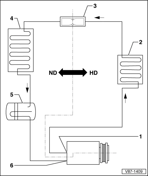
1 - A/C Compressor, HP Side
2 - Condenser
3 - Restrictor
4 - Evaporator
5 - Reservoir
6 - A/C Compressor, LP Side
