Audi Q7: Repair Information
General Repair Information
The highest level of care and cleanliness along with tools that function properly are required to ensure a proper and successful transmission repair. Of course the general safety precautions also apply when carrying out repair work.
A list of general instructions that apply to multiple repair procedures throughout the repair manual are summarized once here under the "Components" section. Refer to → Chapter "Components". They apply to this repair manual.
Safety Precautions and Test Procedures
- Repairs done incorrectly on the rear final drive 0D3 "Sport Differential" could cause the final drive to malfunction.
- Testing, assembling and servicing must be performed by qualified personnel only.
Correct Oil Level
- Make sure the rear final drive is filled to specified oil capacity. Refer to → Chapter "Capacities".
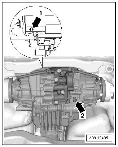
- Fix any leaks on the rear final drive, for example, on the sealing surfaces or the seals. The oil can leak out through the holes between the left -arrow 1- or right -arrow 2- chamber and the rear final drive.
- Rear final drive malfunction.
- Do not drive the rear final drive if there are leaks or insufficient oil.
- Leaks on the rear final drive must be corrected.
- Fill the ATF and/or gear oil if the levels are low. Refer to → Chapter "ATF Level, Checking, 0D3 Sport Differential" and → Chapter "Gear Oil, Checking Level, 0D3 Sport Differential".
- Only use ATF or gear oil available as a replacement part. Refer to the Parts Catalog.
- If the leaks cannot be repaired, then the rear final drive must be replaced.
Rear Final Drive Performance
- Transmission control malfunction.
- Always maintain all specifications when replacing transmission components. Only by doing so assures the performance and the response characteristics of the rear final drive 0D3 "Sport Differential".
Replacing Transmission Components
- When replacing the AWD Control Module -J492-, the adaptation values for the transmission mount (for example clutch wear, oil ageing) must be transmitted with Vehicle Diagnostic Tester otherwise the performance of the rear final drive will be impaired.
- When replacing a chamber or the complete rear final drive, the clutch classification must be entered again in the AWD Control Module -J492-. Refer to Vehicle Diagnostic Tester. If the clutch classification is not performed in the AWD Control Module -J492- then the rear final drive performance will be impaired. When replacing a chamber, the classification identification on the rear final drive housing must be made unrecognizable. The identification of the new classification is made on the new chamber housing.
- Do not place the removed rear final drive on any of the components from the hydraulic control unit (for example, clutch valves). This could damage the components.
Replacing the Oil Pressure/Temperature Sensor -G437- and/or Oil Pressure/Temperature Sensor 2 -G640-.
- The identity of the sensor in the AWD Control Module -J492- must be adapted. Refer to Vehicle Diagnostic Tester after replacing the Oil Pressure/Temperature Sensor -G437- or the Oil Pressure/Temperature Sensor 2 -G640-.
- Do not replace both the Oil Pressure/Temperature Sensor -G437- and Oil Pressure/Temperature Sensor 2 -G640- at the same time because a valid sensor identity is needed for the rear final drive classification to the AWD Control Module -J492-. If the both sensors are replaced at the same time, the AWD Control Module -J492- will interpret this as the rear final drive is being replaced. By doing this, adaptation values in the control module will be erased and the performance of the rear final drive will be impaired.
- If both the Oil Pressure/Temperature Sensor -G437- and Oil Pressure/Temperature Sensor 2 -G640- must be replaced due to mechanical damage, for example, if the connector housing gets damaged, then this must be performed in two steps. After replacing the first sensor, the identity of the must be adapted in the AWD Control Module -J492-. Refer to Vehicle Diagnostic Tester. Do the same for the second sensor.
- If both the Oil Pressure/Temperature Sensor - G437- and Oil Pressure/Temperature Sensor 2 -G640- must be replaced at the same time due to an electrical fault, then the clutch classification must be entered into the AWD Control Module -J492-. Refer to Vehicle Diagnostic Tester. Additionally the ATF must be changed. Refer to → Chapter "ATF, Draining and Filling".
Torque Displacement, Checking
After the following work the function 22- Checking the torque displacement must be performed:
- Working on the rear final drive wiring
- Working on the valves: AWD Clutch Valve -N445- and AWD Clutch Valve 2 -N446-.
- Working on the hydraulic control unit
Vehicle Lift Mode, Vehicles with Air Suspension
Activate the lift mode before lifting the vehicle on a two-column workshop hoist (when there is no weight on the wheels). Refer to → Suspension, Wheels Steering; Rep. Gr.00; Repair Information; Wheel Bearing at Standard Vehicle Height, Lifting Vehicles with Air Suspension.
Special Tools
Refer to the Special Tools Catalog for the complete list of special tools used in this repair manual.
Components
Rear Final Drive
- Allocate bolts and other components according to final drive code using the Parts Catalog.
- When replacing the rear final drive, check the oil level in the rear final drive and fill if necessary. Refer to → Chapter "Gear Oil, Checking Level".
- Capacities and specifications. Refer to → Chapter "Capacities".
- Clean the contact surfaces when installing mounting brackets and waxed components. Contact surfaces must be free of wax and grease.
- Thoroughly clean the connection points and the surrounding area before loosening.
Driveshaft
- The attached driveshaft can only be separated from the transmission if it is completely removed.
- Always remove or install the driveshaft horizontally from the transmission output shaft.
- Always store and transport the driveshaft when it is fully extended.
- The driveshaft can be bent all the way to the center joint without force. Bending the joint forcibly all the way can damage the center joint and/or the protective boot.
- If the driveshaft is separated only from the rear final drive, the driveshaft must be tied up or supported. If necessary, the driveshaft can be bent as far as the end stop of the center without force.
- Pay attention to the tightening sequence for the driveshaft bolt on the rear final drive. Refer to → Fig. "Driveshaft to Rear Final Drive - Tightening Specification and Sequence".
Should there be complaints (noise, vibration), do the following before replacing the driveshaft:
- Remove all the driveshaft bolts from the rear final drive.
- Tighten the driveshaft with new bolts according to the tightening sequence. Refer to → Fig. "Driveshaft to Rear Final Drive - Tightening Specification and Sequence".
- Oil, Environmental and Disposal Regulations
- Handle ATF, transmission fluid and other oils with care.
- Dispose of drained fluid properly.
- Follow the legal, environmental, and disposal regulations.
- Follow the instructions listed on the fluid packaging.
O-Rings, Gaskets and Seals
- O-rings, gaskets and seals must always be replaced.
- After removing the seals, examine the contact surface on the housing or shaft for burrs resulting from removal or for other signs of damage.
- Thoroughly clean the housing separating surfaces before assembling.
- Lightly lubricate the O-rings before inserting to prevent the rings from being crushed during assembly.
- Lightly coat the seal on the outer diameter with oil before installing.
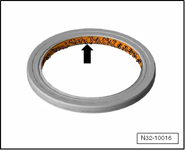
- Fill the space between the sealing lips -arrow- halfway with Sealing Grease -G 052 128 A1-.
- The open side on the shaft seals faces the fluid to be sealed off.
- After replacing the seals, gaskets and O-rings check the gear oil level. Refer to → Chapter "Gear Oil, Checking Level".
Circlips
- Do not stretch the circlips.
- Always replace damaged or stretched circlips.
- The circlips must rest at the bottom of the groove.
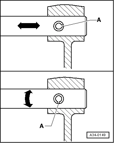
- Replace the adapter sleeves. Installation position: the slot -A- should align with the line of force -arrow-.
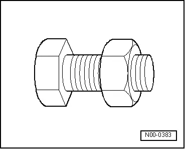
Bolts and Nuts
- Always loosen or tighten bolts and nuts on covers and housings diagonally.
- Parts which are particularly sensitive must not be tilted and must be loosened or tightened diagonally in stages.
- The tightening specifications given apply to unoiled bolts and nuts.
- Always replace self-locking bolts and nuts.
- Clean threads of bolts that were applied with locking fluid using a wire brush (does not apply to driveshaft bolts: these must be replaced). Then insert the bolts with Locking Fluid -AMV 185 101 A1-.
- If self-locking bolts were installed or if regular bolts were installed with locking fluid, then the threaded holes must be cleaned, for example with a thread tap. Otherwise there is the risk that the bolts could break off the next time they are removed.
Contact Corrosion
Contact corrosion can occur if inadequate fasteners (bolts, nuts, washers, etc.) are used.
For this reason, only fasteners with a special surface coating may be installed.
Furthermore, all rubber or plastic and adhesive are made of non-conductive materials.
If there are doubts about whether parts can be used or not, use new parts. Refer to the Parts Catalog.
Note:
- Only original replacement parts are recommended. They are checked and are compatible with aluminum.
- The use of Audi accessories is recommended.
- Contact corrosion damage is not covered under warranty.

