Audi Q7: Speaker Trim, Removing and Installing
Special tools and workshop equipment required
- Wedge Set -T10383-
Removing the Center Speaker Trim
 Caution
There is a risk of damaging the speaker trim.
Proceed very carefully when removing and installing.
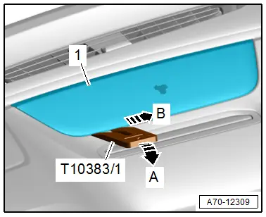
- Carefully detach the speaker trim -1- using the -T10383/1- in direction of -arrow A- by sliding the wedge approximately 2 mm in the seam under the speaker trim.
- Disengage the remaining tabs for the speaker trim along the seam in the direction of -arrow B-.
- If necessary, insert a long screwdriver forward under the speaker trim and disengage the front retaining pin.
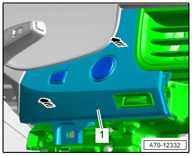
Removing the Exterior Speaker Trim
 Caution
There is a risk of damaging the speaker trim.
Proceed very carefully when removing and Installing.
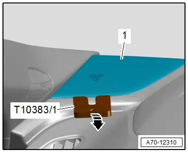
- Carefully detach the speaker trim -1- using the -T10383/1- along the seam -arrow-, to do this push the wedge approximately 2 mm in the seam under the speaker trim.
Installing
Install in reverse order of removal.
Installation notes, for example tightening specifications, replacing components. Refer to → Chapter "Overview - Instrument Panel".
Light Switch Trim, Removing and Installing
Special tools and workshop equipment required
- Wedge Set -T10383-
Removing
- Remove the driver side instrument panel side cover. Refer to → Chapter "Instrument Panel Side Cover, Removing and Installing".
- Remove the instrument panel cover on the driver side. Refer to → Chapter "Driver Side Instrument Panel Cover, Removing and Installing".
- Remove the bolt -arrow-.
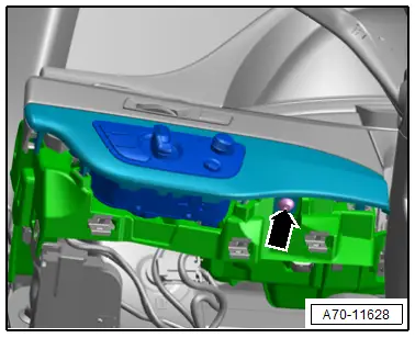
- Unclip the light switch trim -1- with the light switch using the -T10383/1--arrows-.
- Disconnect the connectors and remove the light switch trim with the light switch.
Installing
Install in reverse order of removal.
Information for installation: for example, tightening specifications, replacing body parts. Refer to → Chapter "Overview - Instrument Panel" and → Fig. "Tightening Specification - Light Switch Trim".
Access/Start Authorization Switch Trim, Removing and Installing
Special tools and workshop equipment required
- Wedge Set -T10383-
Removing
- Remove the front passenger side instrument panel side cover. Refer to → Chapter "Instrument Panel Side Cover, Removing and Installing".
- Remove A/C display control head trim. Refer to → Chapter "Display Control Head Trim, Removing and Installing".
- Remove the instrument panel decorative trim on the front passenger side. Refer to → Chapter "Instrument Panel Decorative Trim, Removing and Installing, Front Passenger Side".
- Remove the instrument panel decorative trim in the center. Refer to → Chapter "Instrument Panel Decorative Trim, Removing and Installing, Center".
- Move the steering wheel as far down as possible to do this use the full steering column adjustment range.
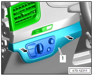
- Unclip the access/start authorization switch trim -1- using the - T10383/1- in direction of -arrow-.
- Disconnect the connectors and remove the access/start authorization switch trim.
Installing
Install in reverse order of removal.
Installation notes, for example tightening specifications, replacing components. Refer to → Chapter "Overview - Instrument Panel".

