Audi Q7: Special Tools
Audi Q7 (4M) 2016-2025 Workshop Manual / Drivetrain / Rear Final Drive, Differential / Special Tools
Special tools and workshop equipment required
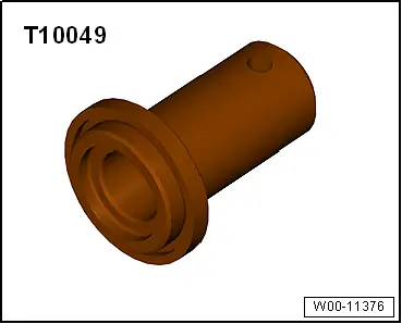
- Seal Installer - Flange Shaft -T10049-
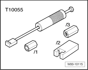
- Puller - Unit Injector -T10055-
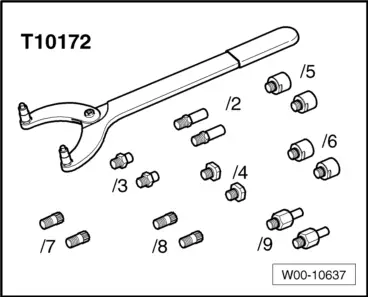
- Counterhold - Kit - Multiple Use -T10172-
- Counterhold - Kit - Adapters 5-9 -T10172/5-
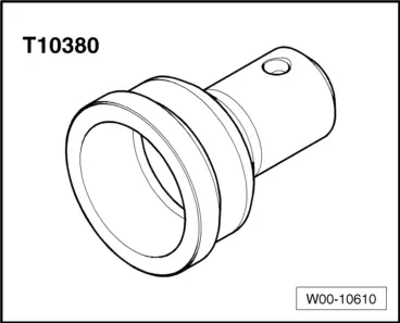
- Seal Installer - Hollow Shaft -T10380-
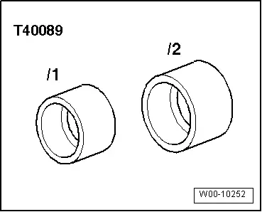
- Press Piece - Deflection Ring -T40089/1-
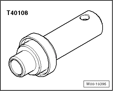
- Seal Installer - Flange Shaft - T40108-
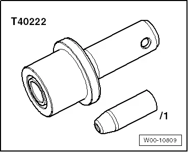
- Seal Installer - Input Shaft - Guide Sleeve -T40222/1-
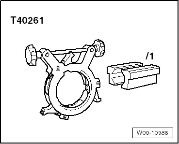
- Flanging Tool -T40261-
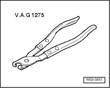
- Hose Clip Pliers -VAG1275A-
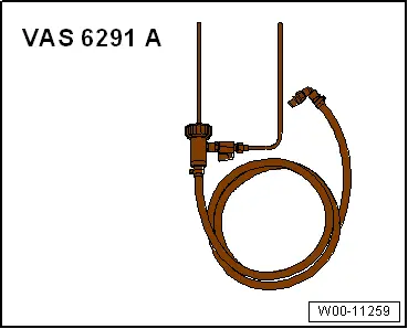
- Charging Device For Haldex Coupling 2 -VAS6291A-
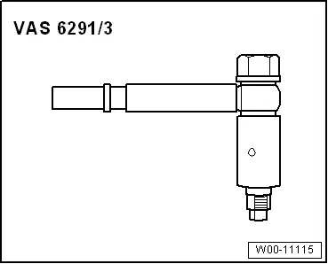
- Charging Device For Haldex Coupling 2 - Adapter 3 -VAS6291/3- (rework if necessary. Refer to → Fig. "Depending on the Version the Spacer Tube from the -VAS6291/3- can Line Up on the Housing Rib on the Final Drive.".)
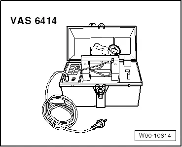
- Inductive Heater -VAS6414-
or
- Commercially Available Hotplate with Digital Thermometer -VAS6519-
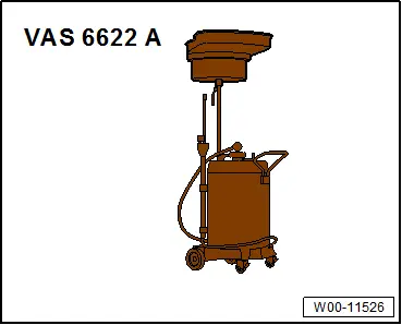
- Used Oil Collection and Extraction Unit -SMN372500-
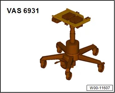
- Engine and Gearbox Jack -VAS6931-
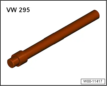
- Bearing/Bushing Installer - Multiple Use -VW295-
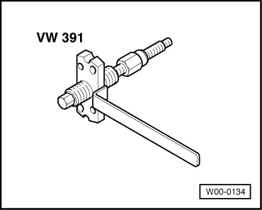
- Puller - Multiple Use -VW391-
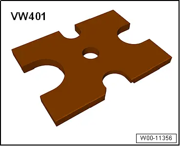
- Press Plate -VW401-
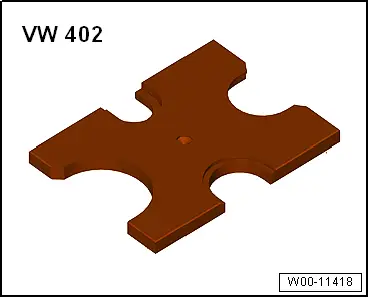
- Press Plate -VW402-
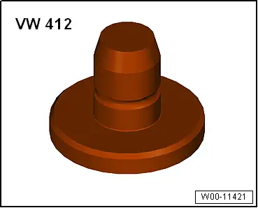
- Press Piece - Multiple Use -VW412-
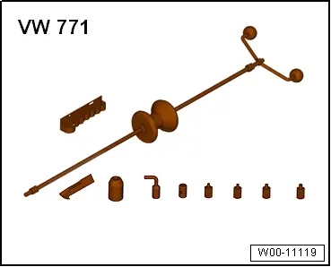
- Slide Hammer Set -VW771-
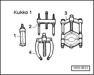
- -3-Puller - Kukko Quick Action Separating Tool 12 to 75 mm -17/1-
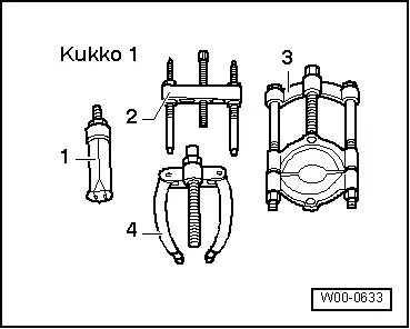
- -3-Puller - Kukko Quick Action Separating Tool - 22-115mm -17/2-, for example.
- Hose Clamp -23 to 35 mm Diameter-
- Drip Tray
- Intake Manifold Release Tool -T10527-
- Puller - Unit Injector - Adapter 2 -T10055/2-
- High Temperature Grease -G 052 133 A3-
- Sealing Grease -G 052 128 A1-
- Two M 8 x 30 Bolts
Revision History
DRUCK NUMBER: A005A011721
