Audi Q7: Stabilizer Bar
Overview - Stabilizer Bar
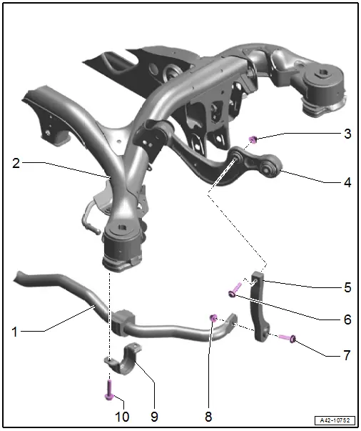
1 - Stabilizer Bar
- Removing and installing. Refer to → Chapter "Stabilizer Bar, Removing and Installing".
- With rubber bushing
- The bonded rubber bushing cannot be replaced separately
2 - Subframe
3 - Nut
- Replace after removing
4 - Transverse Link, Upper Front
5 - Coupling Rod
- Removing and installing. Refer to → Chapter "Coupling Rod, Removing and Installing".
6 - Bolt
- 40 Nm +180º
- Replace after removing
- Must be tightened in the curb weight position. Refer to → Chapter "Wheel Bearing at Standard Vehicle Height, Lifting Vehicles with Air Suspension".
7 - Bolt
- 40 Nm +180º
- Replace after removing
- Must be tightened in the curb weight position. Refer to → Chapter "Wheel Bearing at Standard Vehicle Height, Lifting Vehicles with Air Suspension".
8 - Nut
- Replace after removing
9 - Clamp
10 - Bolt
- 25 Nm +90º
- Replace after removing
Stabilizer Bar, Removing and Installing
Special tools and workshop equipment required
- Torque Wrench 1331 5-50Nm -VAG1331-
- Socket Bit XZN 10 -T10501-
Removing
Before starting work:
- Versions with coil springs: determine the curb weight position. Refer to → Chapter "Wheel Bearing in Curb Weight Position, Lifting Vehicles with Coil Spring".
- Versions with air suspension: determine the standard vehicle height. Refer to → Chapter "Wheel Bearing at Standard Vehicle Height, Lifting Vehicles with Air Suspension".
- Remove the right diagonal brace. Refer to → Body Exterior; Rep. Gr.66; Underbody Trim Panel.
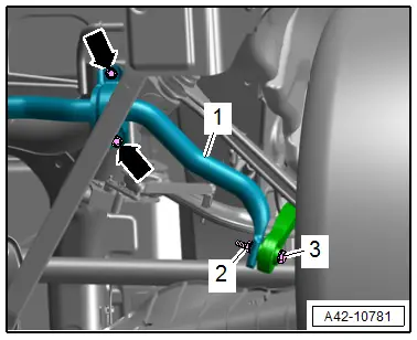
- Remove left and right bolts -arrow- and nut -2-.
- Remove the bolt -3- and stabilizer bar -1-.
Installing
Install in reverse order of removal and note the following:
- Install the threaded connections for the stabilizer bar only until stop but do not yet tighten.
 Note
Note
Bonded rubber bushings have a limited range of motion. Only tighten suspension bolts when vehicle is in curb weight position or at standard vehicle height.
- Lifting the wheel bearing in curb weight position (refer to → Chapter "Wheel Bearing in Curb Weight Position, Lifting Vehicles with Coil Spring") or at standard vehicle height (refer to → Chapter "Wheel Bearing at Standard Vehicle Height, Lifting Vehicles with Air Suspension").
Tightening Specifications
- Refer to → Chapter "Overview - Stabilizer Bar"
Coupling Rod, Removing and Installing
Special tools and workshop equipment required
- Torque Wrench 1331 5-50Nm -VAG1331-
Removing
Before starting work:
- Versions with coil springs: determine the curb weight position. Refer to → Chapter "Wheel Bearing in Curb Weight Position, Lifting Vehicles with Coil Spring".
- Versions with air suspension: determine the standard vehicle height. Refer to → Chapter "Wheel Bearing at Standard Vehicle Height, Lifting Vehicles with Air Suspension".
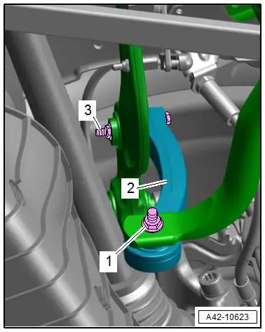
- Disconnect the connectors -1 and 3- and remove the coupling rod -2-.
Installing
Install in reverse order of removal and note the following:
- Install the threaded connections for the coupling rod only until stop but do not yet tighten.
 Note
Note
Bonded rubber bushings have a limited range of motion. Only tighten suspension bolts when vehicle is in curb weight position or at standard vehicle height.
- Lifting the wheel bearing in curb weight position (refer to → Chapter "Wheel Bearing in Curb Weight Position, Lifting Vehicles with Coil Spring") or at standard vehicle height (refer to → Chapter "Wheel Bearing at Standard Vehicle Height, Lifting Vehicles with Air Suspension").
Tightening Specifications
- Refer to → Chapter "Overview - Stabilizer Bar"

