Audi Q7: Overview - Transverse Link
Audi Q7 (4M) 2016-2025 Workshop Manual / Chassis / Suspension, Wheels, Steering / Rear Suspension / Overview - Transverse Link
Upper Transverse Link
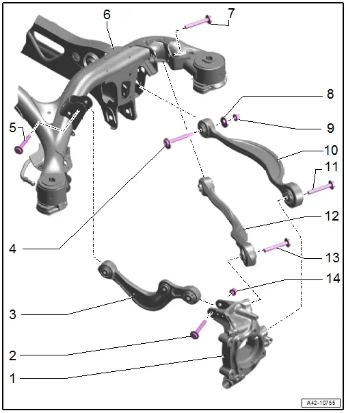
1 - Wheel Bearing Housing
2 - Bolt
- 70 Nm +180º
- Replace after removing
- Must be tightened in the curb weight position. Refer to → Chapter "Wheel Bearing at Standard Vehicle Height, Lifting Vehicles with Air Suspension".
3 - Transverse Link, Upper Front
- Removing and installing. Refer to → Chapter "Upper Transverse Link, Removing and Installing".
4 - Eccentric Bolt
5 - Bolt
- 40 Nm +180º
- Replace after removing
- Must be tightened in the curb weight position. Refer to → Chapter "Wheel Bearing at Standard Vehicle Height, Lifting Vehicles with Air Suspension".
6 - Subframe
7 - Bolt
- 70 Nm +180º
- Replace after removing
- Must be tightened in the curb weight position. Refer to → Chapter "Wheel Bearing at Standard Vehicle Height, Lifting Vehicles with Air Suspension".
8 - Eccentric Washer
9 - Nut
- 110 Nm
- Replace after removing
- Loosen and tighten using the 21 mm internal multi-point socket
- Must be tightened in the curb weight position. Refer to → Chapter "Wheel Bearing at Standard Vehicle Height, Lifting Vehicles with Air Suspension".
10 - Tie Rod
- Removing and installing. Refer to → Chapter "Tie Rod, Removing and Installing".
11 - Bolt
- 100 Nm +180º
- Replace after removing
- Must be tightened in the curb weight position. Refer to → Chapter "Wheel Bearing at Standard Vehicle Height, Lifting Vehicles with Air Suspension".
12 - Upper Rear Transverse Link
- Removing and installing. Refer to → Chapter "Rear Upper Transverse Link, Removing and Installing".
13 - Bolt
- 100 Nm +180º
- Replace after removing
- Must be tightened in the curb weight position. Refer to → Chapter "Wheel Bearing at Standard Vehicle Height, Lifting Vehicles with Air Suspension".
14 - Nut
- Replace after removing
Lower Transverse Link
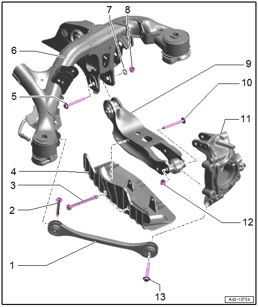
1 - Front Lower Transverse Link
- Removing and installing. Refer to → Chapter "Front Lower Transverse Link, Removing and Installing".
2 - Bolt
- 40 Nm +180º
- Replace after removing
- Must be tightened in the curb weight position. Refer to → Chapter "Wheel Bearing at Standard Vehicle Height, Lifting Vehicles with Air Suspension".
3 - Retaining Pin
4 - Wind Deflector
5 - Eccentric Bolt
6 - Subframe
7 - Eccentric Washer
8 - Nut
- 160 Nm
- Replace after removing
- Must be tightened in the curb weight position. Refer to → Chapter "Wheel Bearing at Standard Vehicle Height, Lifting Vehicles with Air Suspension".
- Loosen and tighten using the 21 mm 6-edge wrench
9 - Rear Lower Transverse Link
- Removing and installing. Refer to → Chapter "Rear Lower Transverse Link, Removing and Installing".
10 - Bolt
- Replace after removing
11 - Wheel Bearing Housing
12 - Nut
- 130 Nm +180º
- Replace after removing
- Must be tightened in the curb weight position. Refer to → Chapter "Wheel Bearing at Standard Vehicle Height, Lifting Vehicles with Air Suspension".
13 - Bolt
- 70 Nm +180º
- Replace after removing
- Must be tightened in the curb weight position. Refer to → Chapter "Wheel Bearing at Standard Vehicle Height, Lifting Vehicles with Air Suspension".

