Audi Q7: Camshaft Adjustment Valve 1 - N205-, Checking
General Description
The camshaft's task is to operate the valves at the right time and in the right order to control the charge cycle. Camshaft adjustment using the Camshaft Adjustment Valve 1 -N205- varies the opening times of the valves to suit all operating conditions. This ensures ideal charge cycles within a wide range of engine speeds and loads. Fuel consumption and pollutant emissions are reduced, torque and smoothness increased. In engines with a double overhead camshaft the size and positioning of the valve opening overlap can be influenced, enhancing characteristics in full-load and part-load operation. In continuous camshaft adjustment, the adjustment is infinitely variable within specific parameters.
Special tools and workshop equipment required
- Multimeter.
- Wiring Diagram.
- Scan Tool.
Test requirements
- Fuses OK.
- Battery voltage OK.
- Switch OFF all electrical and electronic accessories.
- Vehicles with automatic transmission, ensure the selector lever position is in "P".
- Vehicles with manual transmission, ensure the shifter lever position is in "N" with the parking brake applied.
- Coolant temperature: ≥ 80º C.
- Observe all safety precautions: → Chapter "Safety Precautions".
- View clean working conditions: → Chapter "Clean Working Conditions".
- For Hybrid vehicles, refer to: → Chapter "High Voltage System General Warnings".
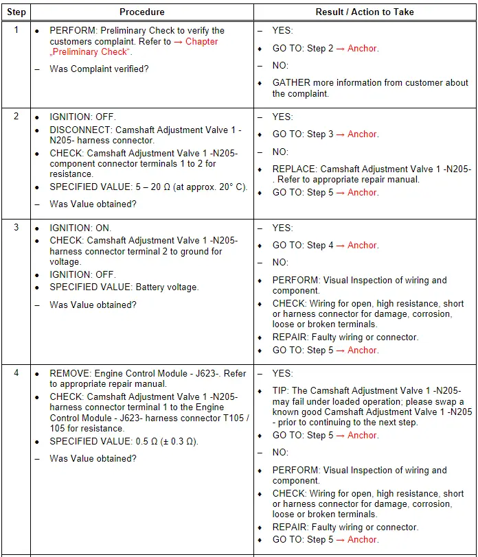
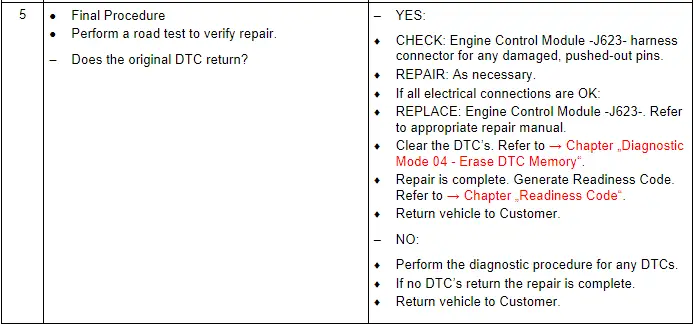
Test Procedure
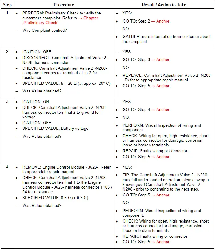
Camshaft Adjustment Valve 2 - N208-, Checking
General Description
The camshaft's task is to operate the valves at the right time and in the right order to control the charge cycle. Camshaft adjustment using the Camshaft Adjustment Valve 2 - N208 - varies the opening times of the valves to suit all operating conditions. This ensures ideal charge cycles within a wide range of engine speeds and loads. Fuel consumption and pollutant emissions are reduced, torque and smoothness increased. In engines with a double overhead camshaft the size and positioning of the valve opening overlap can be influenced, enhancing characteristics in full-load and part-load operation. In continuous camshaft adjustment, the adjustment is infinitely variable within specific parameters.
Special tools and workshop equipment required
- Multimeter.
- Wiring Diagram.
- Scan Tool.
Test requirements
- Fuses OK.
- Battery voltage OK.
- Switch OFF all electrical and electronic accessories.
- Vehicles with automatic transmission, ensure the selector lever position is in "P".
- Vehicles with manual transmission, ensure the shifter lever position is in "N" with the parking brake applied.
- Coolant temperature: ≥ 80º C.
- Observe all safety precautions: → Chapter "Safety Precautions".
- View clean working conditions: → Chapter "Clean Working Conditions".
- For Hybrid vehicles, refer to: → Chapter "High Voltage System General Warnings".
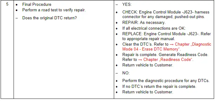
Test Procedure