Audi Q7: Cylinder Block, Belt Pulley Side
Overview - Ribbed Belt Drive
Overview - Ribbed Belt Drive, Supercharger Ribbed Belt
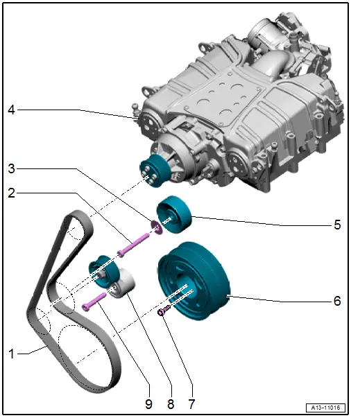
1 - Ribbed Belt
- For the supercharger
- Check for wear
- Removing and installing. Refer to → Chapter "Ribbed Belt, Removing and Installing, Supercharger Ribbed Belt".
- When installing, make sure it is seated correctly on the ribbed belt pulleys
2 - Bolt
- 40 Nm
- 37 Nm when using Wrench - Door Adjusting -3320-
- Not available separately, one unit with -5-
3 - Washer
- Not available separately, one unit with -5-
4 - Supercharger
- Overview. Refer to → Chapter "Overview - Supercharger".
5 - Idler Roller
- For the ribbed belt
- One unit with -2, 3-
6 - Vibration Damper
- With the ribbed belt pulley
- Installation is only possible in one position because of the offset holes
- Removing and installing. Refer to → Chapter "Vibration Damper, Removing and Installing".
7 - Bolt
- Tightening specification. Refer to -item 1-
8 - Tensioner
- For the ribbed belt
- Removing and installing. Refer to → Chapter "Ribbed Belt Tensioner, Removing and Installing, Supercharger Ribbed Belt".
9 - Bolt
- 40 Nm
Overview - Ribbed Belt Drive, Sub-Assembly Ribbed Belt
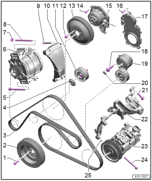
1 - Bolt
- 20 Nm +90º
- Replace after removing
2 - Vibration Damper
- With double ribbed belt pulley
- Removing and installing. Refer to → Chapter "Vibration Damper, Removing and Installing".
3 - Ribbed Belt
- Check for wear
- Before removing, mark the running direction using chalk or felt-tip pen
- Removing and installing. Refer to → Chapter "Ribbed Belt, Removing and Installing, Sub-Assembly Ribbed Belt".
- Do not kink
- When installing, make sure it is seated correctly on the ribbed belt pulleys
4 - Cover
- For the idler roller
- Depending on the version
5 - Bolt
- Tightening specification. Refer to → Electrical Equipment; Rep. Gr.27; Generator; Overview - Generator.
6 - Generator
- Removing and installing. Refer to → Electrical Equipment; Rep. Gr.27; Generator; Generator, Removing and Installing.
7 - Nut
- Tightening specification. Refer to → Electrical Equipment; Rep. Gr.27; Generator; Overview - Generator.
8 - Threaded Pin
- Tightening specification. Refer to → Electrical Equipment; Rep. Gr.27; Generator; Overview - Generator.
9 - Bolt
- 20 Nm
10 - Bracket
- For the generator
11 - Idler Roller
- 40 Nm
- For the ribbed belt
12 - Bolt
- Tightening specification. Refer to -item 14-
13 - Ribbed Belt Pulley
- For the coolant pump
- Removing and installing. Refer to → Chapter "Coolant Pump, Removing and Installing".
14 - Bolt
- Tightening specification. Refer to -item 12-
15 - Coolant Pump
- Removing and installing. Refer to → Chapter "Coolant Pump, Removing and Installing".
16 - Bolt
- Tightening specification and sequence. Refer to → Fig. "Ribbed Belt Pulley Side Sealing Flange - Tightening Specifications and Sequence".
17 - Sealing Flange, Belt Pulley Side
- Replacing. Refer to → Chapter "Sealing Flange, Removing and Installing, Belt Pulley Side".
18 - Bolt
- 40 Nm
19 - Tensioner
- For the ribbed belt
- Removing and installing. Refer to → Chapter "Ribbed Belt Tensioner, Removing and Installing, Sub-Assembly Ribbed Belt".
20 - Cover
- For the tensioner
21 - Bolt
- M8 tightening specification: -item 3-
- M10 tightening specification: -item 7-
22 - Left Engine Support
- With A/C compressor bracket
23 - A/C Compressor
- Do not unfasten/separate refrigerant lines
- Removing and installing. Refer to → Heating, Ventilation and Air Conditioning; Rep. Gr.87; A/C Compressor; A/C Compressor, Removing and Installing at Bracket.
24 - Bolt
- Tightening specification. Refer to → Heating, Ventilation and Air Conditioning; Rep. Gr.87; A/C Compressor; Overview - A/C Compressor Power Unit.
25 - Alignment Sleeve
- Quantity: 2
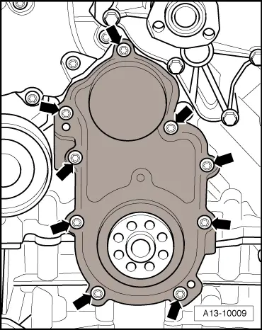
Ribbed Belt Pulley Side Sealing Flange - Tightening Specifications and Sequence
- Tighten the bolts -arrows- diagonally in stages to 9 Nm.
Ribbed Belt, Removing and Installing
Ribbed Belt, Removing and Installing, Supercharger Ribbed Belt
Special tools and workshop equipment required
- Locking Pin -T10060A-
Removing
 WARNING
There is a risk of injury if the radiator fan turns on by itself.
The radiator fans can come on by itself even when the ignition is turned off, such as when heat builds up in the engine compartment.
- Remove the front noise insulation. Refer to → Body Exterior; Rep. Gr.66; Noise Insulation; Noise Insulation, Removing and Installing.
 Caution
Risk of destroying by reversing the running direction on a used ribbed belt.
Before removing the ribbed belt, mark the running direction with chalk or a felt-tip pen for reinstallation.
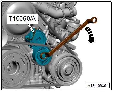
- Pivot the tensioner clockwise in direction of -arrow- to release the tension on the ribbed belt.
- Remove the ribbed belt and secure the tensioner with Locking Pin -T10060A-.
Installing
Install in reverse order of removal and note the following:
- Place the ribbed belt over the ribbed belt pulleys as shown.
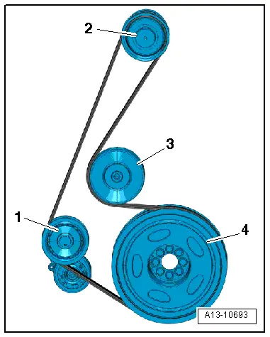
1 - Tensioner
2 - Supercharger
3 - Idler Roller
4 - Vibration Damper
- Lastly, place the ribbed belt on the idler roller -3-.
 Note
Note
When installing the ribbed belt, make sure it is seated correctly on the ribbed belt pulleys.
- Start the engine and check the ribbed belt routing.
Tightening Specifications
- Refer to → Body Exterior; Rep. Gr.66; Noise Insulation; Overview - Noise Insulation.
Ribbed Belt, Removing and Installing, Sub-Assembly Ribbed Belt
Special tools and workshop equipment required
- Wrench - Door Adjusting - Box Wrench -3320/2- from Wrench - Door Adjusting -3320-
- Locking Pin -T10060A-
Removing
- Remove the engine cover. Refer to → Chapter "Engine Cover, Removing and Installing".
- Remove the supercharger ribbed belt. Refer to → Chapter "Ribbed Belt, Removing and Installing, Supercharger Ribbed Belt".
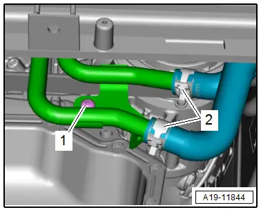
- Remove the bolt -2- on the left front coolant pipes.
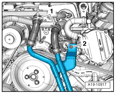
 Note
Note
- For clarity, the installation position is shown with the engine removed.
- Ignore -1-.
- Remove the bolt -1- for the left front coolant pipes.
 Note
Note
Ignore -2-.

 Caution
Risk of destroying by reversing the running direction on a used ribbed belt.
Before removing the ribbed belt, mark the running direction with chalk or a felt-tip pen for reinstallation.
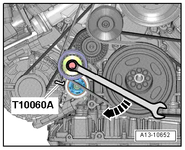
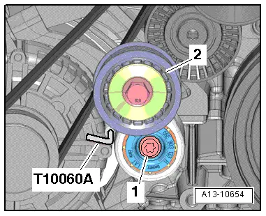
- To release the tension on the ribbed belt, pivot the tensioner clockwise in direction of -arrow- and then lock using a Locking Pin -T10060A-.
- Using the Wrench - Door Adjusting - Box Wrench -3320/2-, remove the bolt -arrow- just until the ribbed belt can be removed.
Installing
Install in reverse order of removal and note the following:
- Place the ribbed belt over the ribbed belt pulleys as shown.
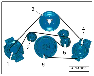
1 - Generator
2 - Idler Roller
3 - Coolant Pump
4 - A/C Compressor
5 - Ribbed Belt Tensioner
6 - Vibration Damper
 Note
Note
When installing the ribbed belt, make sure it is seated correctly on the ribbed belt pulleys.
- Install the supercharger ribbed belt. Refer to → Chapter "Ribbed Belt, Removing and Installing, Supercharger Ribbed Belt".
- Start the engine and check the ribbed belt routing.
- Install the engine cover. Refer to → Chapter "Engine Cover, Removing and Installing".
Tightening Specifications
- Refer to → Chapter "Overview - Ribbed Belt Drive, Sub-Assembly Ribbed Belt"
- Refer to → Chapter "Overview - Coolant Pipes"
Ribbed Belt Tensioner, Removing and Installing
Ribbed Belt Tensioner, Removing and Installing, Supercharger Ribbed Belt
Removing
- Remove the supercharger ribbed belt. Refer to → Chapter "Ribbed Belt, Removing and Installing, Supercharger Ribbed Belt".
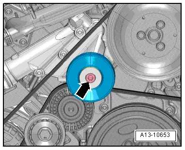
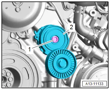
- Remove the bolt -1- and remove the ribbed belt tensioner -2-.
 Note
Note
Ignore the Locking Pin -T10060A-.
Installing
Install in reverse order of removal and note the following:
- Install the supercharger ribbed belt. Refer to → Chapter "Ribbed Belt, Removing and Installing, Supercharger Ribbed Belt".
Tightening Specifications
- Refer to → Chapter "Overview - Ribbed Belt Drive, Supercharger Ribbed Belt"
Ribbed Belt Tensioner, Removing and Installing, Sub-Assembly Ribbed Belt
Removing
 WARNING
There is a risk of injury if the radiator fan turns on by itself.
The radiator fans can come on by itself even when the ignition is turned off, such as when heat builds up in the engine compartment.
- Remove the engine cover. Refer to → Chapter "Engine Cover, Removing and Installing".
- Remove the bolt -2- on the left front coolant pipes.
 Note
Note
Ignore -1-.

- Remove the bolt -1- for the left front coolant pipes.
 Note
Note
Ignore -2-.
- Pivot the tensioner clockwise in direction of -arrow- to release the tension on the ribbed belt.
- Remove the ribbed belt from the tensioner and release the tension on the tensioner.
 Note
Note
Ignore the Locking Pin -T10060A-.

- Remove the bolt -1- and then remove the ribbed belt tensioner -2- from the cylinder block.
Installing
Install in reverse order of removal and note the following:
- Install the ribbed belt. Refer to → Chapter "Ribbed Belt, Removing and Installing, Sub-Assembly Ribbed Belt".
- Install the engine cover. Refer to → Chapter "Engine Cover, Removing and Installing".
Tightening Specifications
- Refer to → Chapter "Overview - Ribbed Belt Drive, Sub-Assembly Ribbed Belt"
- Refer to → Chapter "Overview - Coolant Pipes"
Vibration Damper, Removing and Installing
Special tools and workshop equipment required
- Wrench - Pin Type -3036-
 Caution
This procedure contains mandatory replaceable parts. Refer to component overview prior to starting procedure.
Mandatory Replacement Parts
- Bolts - Vibration Damper
Removing
- Remove the supercharger ribbed belt. Refer to → Chapter "Ribbed Belt, Removing and Installing, Supercharger Ribbed Belt".
- Remove the ribbed belt from the tensioner and release the tension on the tensioner. Refer to → Chapter "Ribbed Belt Tensioner, Removing and Installing, Sub-Assembly Ribbed Belt".
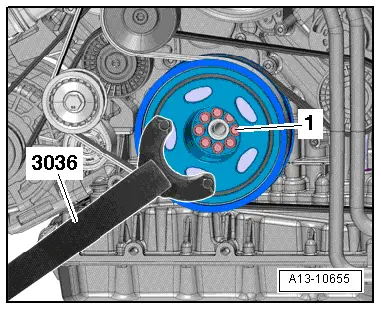
- Counterhold with the Wrench - Pin Type -3036- and loosen the bolts -1- for the vibration damper.
- Remove the bolts and remove the vibration damper.
Installing
Install in reverse order of removal and note the following:
 Note
Note
- Replace the bolts that were tightened with an additional turn after removing them.
- Installation is possible in one position only.
- Pay attention to the alignment sleeve when installing the vibration damper.
- Install the ribbed belt. Refer to → Chapter "Ribbed Belt, Removing and Installing, Sub-Assembly Ribbed Belt".
Tightening Specifications
- Refer to → Chapter "Overview - Ribbed Belt Drive, Sub-Assembly Ribbed Belt"
Engine Support, Removing and Installing
Removing
- Remove the engine mount. Refer to → Chapter "Engine Mount, Removing and Installing".
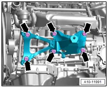
Left Engine Support:
- Remove the bolts -arrows- and the engine support.
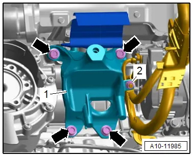
Right Engine Support:
- Remove the nut -2- and free up the ground wire at the engine support -1-.
- Remove the bolts -arrows- and the engine support.
Installing
Install in reverse order of removal and note the following:
- Install the engine mount. Refer to → Chapter "Engine Mount, Removing and Installing".
- Connections and wire routing. Refer to → Wiring diagrams, Troubleshooting & Component locations.
Tightening Specifications
- Refer to → Chapter "Overview - Subframe Mount"
Sealing Flange, Removing and Installing, Belt Pulley Side
Special tools and workshop equipment required
- Wrench - Pin Type -3212-
- Assembly Tool -T40048A-
- Hand Drill with Plastic Brush Attachment
- Protective Eyewear
- Sealant. Refer to the Parts Catalog.
Procedure
- Remove the vibration damper. Refer to → Chapter "Vibration Damper, Removing and Installing".
- Remove the lock carrier cover. Refer to → Body Exterior; Rep. Gr.63; Front Bumper; Attachments, Removing and Installing.
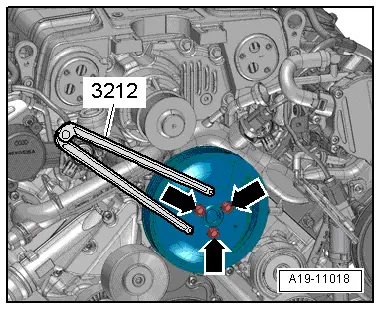
- Remove the bolts -arrows- for the coolant pump ribbed belt pulley by using a Wrench - Pin Type -3212- to counterhold.
- Remove the bolts and remove the ribbed belt pulley.
- Loosen and remove the bolts -arrows- in a diagonal sequence.
- Loosen the sealing flange on the ribbed belt side from the bond and then remove it.
 Note
Note
Replace the belt pulley side sealing flange after removal.

 Caution
Risk of contaminating the lubricating system.
Cover open engine components.
 WARNING
Risk of eye injury.
Wear protective eyewear!
- Remove the sealant residue on the cylinder block and the oil pan upper section -1-, for example using a rotating plastic brush.
- Clean any oil or grease off the sealing surfaces.

 Note
Note
Note the expiration date for the sealant.
- Cut the tube nozzle at the front marking (nozzle diameter: approximately 1.5 mm).
 Caution
There is a risk that the lubrication system could be blocked by excess sealant.
Do not apply sealant bead thicker than indicated.
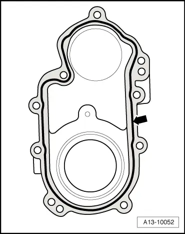
- Apply the sealant bead -arrow- to the sealing surface of the new ribbed belt side sealing flange as shown.
- The groove on the sealing surface must be completely filled with sealant.
- The sealant bead must be 1.5 to 2.0 mm above the sealing surface.
 Note
Note
The ribbed belt side sealing flange must be installed within five minutes of applying the sealant.
- Attach the Assembly Tool - Mounting Aid -T40048/1- to the Assembly Tool - Pulling Sleeve -T40048/2- and slide the sealing flange -1- onto the pulling sleeve.
- Remove the mounting aid.
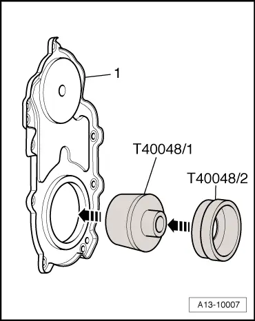
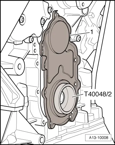
- Then position the sealing flange -1- with the installed Assembly Tool - Pulling Sleeve -T40048/2- on the crankshaft.
- Push the sealing flange onto the engine sealing surface and fasten it without tilting it. Refer to → Fig. "Ribbed Belt Pulley Side Sealing Flange - Tightening Specifications and Sequence".
Installation is performed in reverse order of removal, while noting the following:
- Install the lock carrier cover. Refer to → Body Exterior; Rep. Gr.63; Front Bumper; Attachments, Removing and Installing.
- Install the vibration damper. Refer to → Chapter "Vibration Damper, Removing and Installing".
Tightening Specifications
- Refer to → Fig. "Ribbed Belt Pulley Side Sealing Flange - Tightening Specifications and Sequence"
- Refer to → Chapter "Overview - Coolant Pump/Coolant Thermostat"

