Audi Q7: Subframe Mount
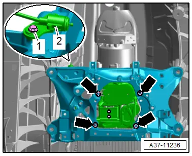
Overview - Subframe Mount
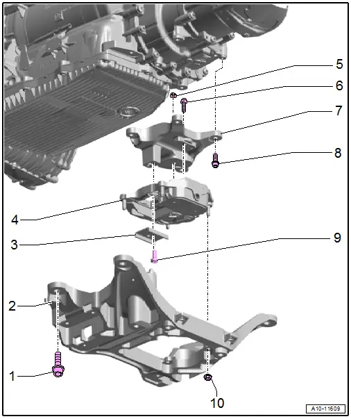
1 - Bolt
- 55 Nm
2 - Tunnel Crossmember
- Removing and installing. Refer to → Chapter "Tunnel Crossmember, Removing and Installing".
3 - Stop
- For the transmission mount
4 - Transmission Mount
- Removing and installing. Refer to → Rep. Gr.10; Subframe Mount; Transmission Mount, Removing and Installing.
5 - Nut
- 20 Nm
- Only remove if the transmission mount must be separated from the transmission support
6 - Bolt
- 20 Nm
7 - Transmission Support
- Removing and Installing
8 - Bolt
- 40 Nm
9 - Bolt
- 20 Nm +90º
- Replacing
- Only remove if the transmission mount must be separated from the transmission support
10 - Nut
- 20 Nm
Tunnel Crossmember, Removing and Installing
Tunnel Crossmember, Removing and Installing, Vehicles with 3.0L TFSI Engine
Special tools and workshop equipment required
- Engine and Gearbox Jack -VAS6931-
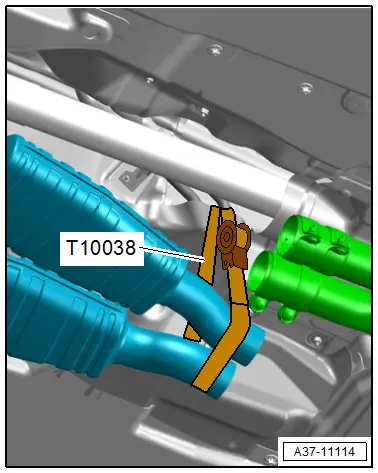
- Tensioning Strap -T10038-
- Engine/Gearbox Jack - Gearbox Support -T10337-
Removing
- Remove the rear noise insulation. Refer to → Body Exterior; Rep. Gr.66; Noise Insulation; Noise Insulation, Removing and Installing.
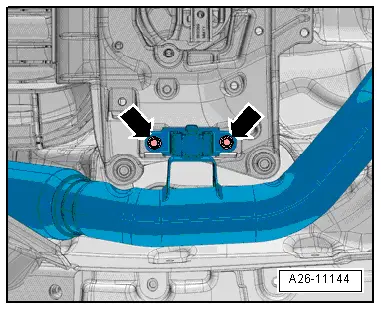
- Remove the left and right bolts -arrows- for the front muffler.
- Loosen the clamping sleeves -1 and 2-.
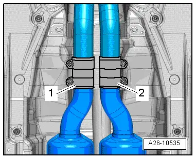
- Push the clamping sleeves toward the rear lower the front muffler slightly and tie up with the Tensioning Strap -T10038- as shown.
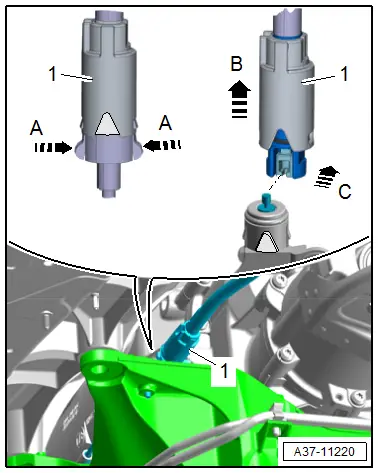
- Release the retainers in the direction of -arrows A- and slide the sleeve -1- on the emergency release cable in the direction of -arrow B-.
- Disconnect the rear emergency release cable from the front emergency release cable in the direction of -arrow C-.
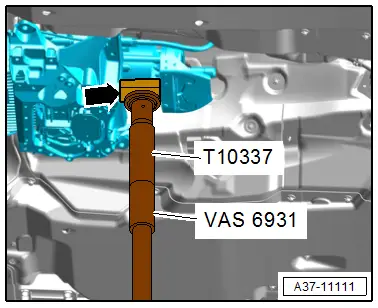
- Mount the Engine/Gearbox Jack - Gearbox Support -T10337- on the Engine and Gearbox Jack -VAS6931- and attach it under the transmission.
 Note
Note
To prevent damage to the driveshaft heat shield, place a suitable piece of wood -arrow- underneath.
- Raise the transmission slightly.
 WARNING
There is the risk of an accident.
The Engine and Gearbox Jack -VAS6931- may only be used during assembly and must not sit unsupervised under the vehicle.
- Remove the bolts from the tunnel crossmember -arrows-.
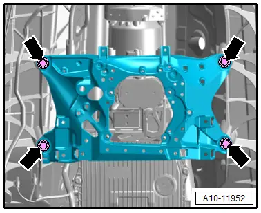
- Remove the nuts -arrows- and lower the tunnel crossmember -3- slightly.
- Remove the bolt -1- and free up the rear emergency release cable -2-.
- Remove the tunnel crossmember.
Installing
Install in the reverse order of removal while noting the following:
- Install the parking lock emergency release cable. Refer to → Chapter "Front Parking Lock Emergency Release Cable, Removing and Installing".
Tightening Specifications
- Refer to → Chapter "Overview - Subframe Mount"
- Refer to → Rep. Gr.26; Emissions Control System; Overview - Emissions Control System.
- Refer to → Body Exterior; Rep. Gr.66; Noise Insulation; Overview - Noise Insulation.
Transmission, Transporting
Special tools and workshop equipment required
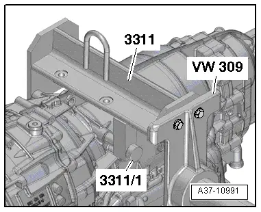
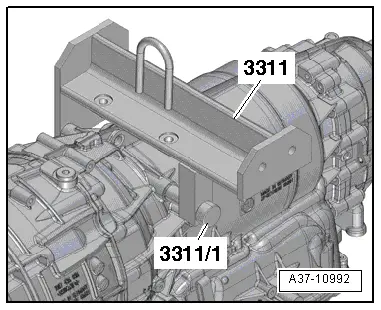
- Hook And Support Tool -3311- with Hook And Support Tool - Bolt -3311/1-
- Shop Crane -VAS6100-
Procedure
- Transmission removed. Refer to → Chapter "Transmission, Removing and Installing".
 Caution
Transmission components could be damaged if they are not set down correctly.
Do not place the transmission on the ATF cooler or oil pan.
 WARNING
An accident could result if the transmission is not secured correctly.
- Exchange the bolt on the Hook and Support Tool -3311- for a new, longer Hook And Support Tool - Bolt -3311/1-.
- Only this way can the transmission be secured.
- Secure the transmission on the Hook And Support Tool -3311- (use new longer bolts Hook And Support Tool - Bolt -3311/1-).
- Lift and transport the transmission with the Shop Crane -VAS6100-.
Securing on Engine and Transmission Holder
Special tools and workshop equipment required
- Holding Plate -VW309A-
- Engine and Gearbox Bracket -VAS6095A-
- Shop Crane -VAS6100-
Procedure
- Hold the transmission with the Shop Crane -VAS6100-. Refer to → Chapter "Transmission, Transporting".
- Attach the Holding Plate -VW309A- to the Hook And Support Tool -3311-.
- Place the transmission using the Shop Crane -VAS6100- in the Engine And Transmission Holder -VAS6095-.
 Note
Note
The vents for the transmission housing and final drive must be closed before turning a filled transmission with ATF pan upward on the engine/transmission holder.