Audi Q7: Refrigerant Circuit Components
 Caution
Non-approved tools or materials such as leak sealing additives can cause damage or malfunctions in the system.
Only use tools and materials approved by the manufacturer.
The warranty is voided if non-approved tools or materials are used.
- Any refrigerant circuit components submitted for quality observation must be sealed (use the caps that come with the replacement part).
- Replace damaged or leaking components of the refrigerant circuit. Refer to → Chapter "Refrigerant Circuit Components, Replacing".
 Note
Note
To date, the following replacement parts (A/C compressor, reservoir, evaporator and condenser) are filled with nitrogen gas. This charge is being gradually discontinued. Little or no pressure equalization is therefore noticeable on unscrewing sealing plugs from replacement parts.
Refrigerant Circuit Components Allocation, High and Low Pressure Sides
General Information
High pressure side are the condenser, receiver/dryer and restrictor or expansion valve to separate the high and low pressure liquid ends.
High pressure results from the restrictor or expansion valve forming a constriction and causing the refrigerant to accumulate, thus leading to an increase in pressure and temperature.
Excess pressure occurs if too much refrigerant or refrigerant oil is used, the condenser is contaminated, the radiator fan is malfunctioning, the system is blocked or there is moisture in the refrigerant circuit (icing-up of restrictor or expansion valve).
Low pressure side are the evaporator, reservoir, evaporator temperature sensor and A/C compressor to separate high and low pressure gas ends.
A drop in system pressure can be caused by loss of refrigerant, the restrictor or expansion valve (no constriction), a malfunctioning A/C compressor or an iced-up evaporator.
Mechanically Driven A/C Compressor
The A/C compressor is driven by a ribbed belt or a input shaft, which is driven by the vehicle engine.
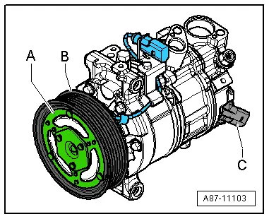
A/C Compressor with A/C Clutch
- An electromagnetic clutch -A- attached to A/C compressor provides the power link between the ribbed belt pulley -B- and A/C compressor crankshaft with A/C system switched on.
- An overload safeguard attached to the clutch plate or in the A/C compressor solenoid coil is tripped if the compressor does not move freely, thus protecting the belt drive against overload.
A/C Compressor without A/C Clutch
- An overload safeguard attached to the pulley of the compressor -B- is tripped if the compressor does not move freely, thus protecting the belt drive against overload.
All A/C Clutch
The A/C compressor extracts the refrigerant gas from the evaporator, compresses it and relays it to the condenser.
 Note
Note
- The A/C compressor contains refrigerant oil, which can be mixed with refrigerant R134a under any temperature.
- The data plate lists the type of refrigerant required for the A/C compressor. A regulator valve regulates pressure within the specified range (control characteristics) on the low pressure side.
- A/C compressors with or without an A/C clutch are currently controlled externally by a regulator valve -C-.
- On A/C compressors without an A/C clutch, the engine is only to be started following complete assembly of the refrigerant circuit.
- So that the A/C compressor does not get damaged when the refrigerant circuit is empty, the A/C clutch is turned off and the A/C Compressor Regulator Valve -N280- is no longer activated (A/C compressor runs at idle with engine).
- If the refrigerant circuit is empty, a A/C compressor without A/C Clutch -N25- with (A/C Compressor Regulator Valve -N280-) is switched to internal lubrication by way of a valve.
- Depending on the A/C compressor version, there may be a valve installed on the high pressure side of the A/C compressor, which prevents the liquid refrigerant from flowing back into the compressor once the A/C is turned off. If an A/C compressor with this valve is installed in a vehicle with a refrigerant circuit having an expansion valve, then it may take some time until the pressure in the high pressure side decreases (the expansion is cold and the pressure in the low pressure side quickly increases after it is turned off, the expansion valve closes and the refrigerant flows slowly into the low pressure side). If the A/C compressor is switched on, the pressure on the low pressure side goes down, the expansion valve open and the refrigerant can flow of the low pressure side.
- The electromagnetic clutch -A- is activated only when the regulator valve -C- is activated on an A/C compressor with an electromagnetic clutch -A- and with a regulator valve -C-. Refer to → Heating, Ventilation and Air Conditioning; Rep. Gr.87; System Overview - Refrigerant Circuit.
Electrically Driven A/C Compressor for Vehicles with High Voltage System
Vehicles with a High-Voltage System (Hybrid Vehicles)
Extremely Dangerous Due to High-Voltage
The high-voltage system is under high-voltage. Death or serious bodily injury by electric shock.
- Individuals with electronic/medical life- and health sustaining machines in or on their person cannot perform any work on high-voltage systems. Life- and health sustaining machines are for example pain killer pumps, implanted defibrillators, pacemakers, insulin pumps, and hearing aids.
- Have the high-voltage system de-energized by a qualified person.
There is a Risk Of Injury from the Engine Starting Unexpectedly
On electric - hybrid vehicles an active ready mode is difficult to identify. Parts of the body can be clamped or pulled.
- Turn off the ignition.
- Place the ignition key outside of the vehicle interior.
Risk of Damaging the High-Voltage Cables
Misuse can damage the insulation of high-voltage cables or high-voltage connectors.
- Never support objects on the high-voltage cables and the high-voltage connectors.
- Never support tools on the high-voltage cables and the high-voltage connectors.
- Never sharply bend or kink the high-voltage cables.
- When connecting pay attention to the coding of the high-voltage connectors.
- For all procedures on vehicles with high-voltage system pay attention to the additional warning message for these vehicles. Refer to → Chapter "Warnings when Working on Vehicles with High Voltage System".
- If procedures are necessary near components of the high-voltage system "perform a visual inspection of the damage of the high-voltage components and lines". Refer to → Chapter "Performing a Visual Inspection of Damage to High Voltage Components and Cables".
- If work on the components of the high-voltage system is necessity, de-energize the high-voltage system. Refer to → Rep. Gr.93; High-Voltage System, De-Energizing or → Electrical Equipment; Rep. Gr.93; High-Voltage System, De-Energizing.
- Charge the vehicle battery, for example, using the Battery Charger -VAS5904- in the battery support mode to minimize the number of automatic starts during the test- and measuring procedures while the ready mode is active. Refer to → Electrical Equipment General Information; Rep. Gr.27; Battery, Charging and → High Voltage Vehicle General Information; Rep. Gr.93; High-Voltage System General Warnings.
- For testing and measurement procedures that require the ready mode to be active or the ignition to be switched on, the selector lever must be in the "P" position and the parking brake must be activated. The required tools must be placed so that they do not come into contact with any rotating components in the engine and they must also not go into the vicinity of the rotating components when the engine is running.

