Audi Q7: Tail Lamps
Overview - Body Tail Lamps
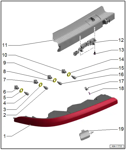
1 - Tail Lamp
- There are different versions. Refer to the Parts Catalog.
- Removing and installing. Refer to → Chapter "Tail Lamp, Removing and Installing".
2 - Brake and Tail Lamp Bulb
- Left Brake/Tail Lamp Bulb 3 -M82-
- Right Brake/Tail Lamp Bulb 3 -M83-
- 12 V, 16 W (W16W)
- Bulb, Replacing. Refer to → Chapter "Bumper Cover Tail Lamp Bulbs, Removing and Installing".
3 - Gasket
- Replace if damaged.
4 - Rear Turn Signal Bulb
- Left Rear Turn Signal Bulb 2 -M80-
- Right Rear Turn Signal Bulb 2 -M81-
- 12 V, 21 W
- Bulb, Replacing. Refer to → Chapter "Bumper Cover Tail Lamp Bulbs, Removing and Installing".
5 - Gasket
- Replace if damaged.
6 - Bulb Socket
7 - Bulb Socket
8 - Gasket
- Replace if damaged.
9 - Bulb Socket
10 - Bulb Socket
11 - Lock Carrier Trim Panel
- Removing and installing. Refer to → Body Interior; Rep. Gr.70; Luggage Compartment Trim Panels; Lock Carrier Trim Panel, Removing and Installing
12 - Rear Lid -Closed- Sensor
- Rear Lid -Closed- Sensor 1 -G525-
- Rear Lid -Closed- Sensor 2 -G526-
- Removing and installing. Refer to → Chapter "Rear Lid -Closed- Sensor 1 and 2 -G525-/-G526-, Removing and Installing".
13 - Bolt
- 0.9 Nm
- Quantity: 2
14 - Gasket
- Replace if damaged.
15 - Rear Fog Lamp Bulb
- Left Rear Fog Lamp Bulb -L46-
- Right Rear Fog Lamp Bulb -L47-
- 12 V, 16 W (W16W)
- Bulb, replacing. Refer to → Chapter "Bumper Cover Tail Lamp Bulbs, Removing and Installing".
16 - Back-Up Lamp Bulb
- Left Back-Up Lamp Bulb -M16-
- Right Back-Up Lamp Bulb -M17-
- 12 V, 16 W (W16W)
- Bulb, replacing. Refer to → Chapter "Bumper Cover Tail Lamp Bulbs, Removing and Installing".
17 - Anti-Twist Mechanism
- For bolt
18 - Bolt
- 2.5 Nm
19 - Cap
- For bolt
- In the bumper cover
Overview - Rear Lid Tail Lamps
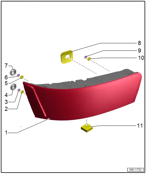
1 - Tail Lamp
- In the rear lid
- Removing and installing. Refer to → Chapter "Rear Lid Tail Lamp, Removing and Installing".
2 - Seal
- Replace if damaged.
3 - Nut
- Tightening specification and sequence. Refer to → Fig. "Tightening Specification and Sequence for the Tail Lamps".
4 - Grommet
5 - Seal
- Replace if damaged.
6 - Nut
- Tightening specification and sequence. Refer to → Fig. "Tightening Specification and Sequence for the Tail Lamps".
7 - Grommet
8 - Seal
- Self-adhesive
- Replace if damaged.
9 - Nut
- Tightening specification and sequence. Refer to → Fig. "Tightening Specification and Sequence for the Tail Lamps".
10 - Seal
- Replace if damaged.
11 - Seal
- Self-adhesive
- Replace if damaged.
Tightening Specification and Sequence for the Tail Lamps
- Tighten the nuts for the tail lamps to 3.5 Nm and in the sequence -1, 2 and 3-.
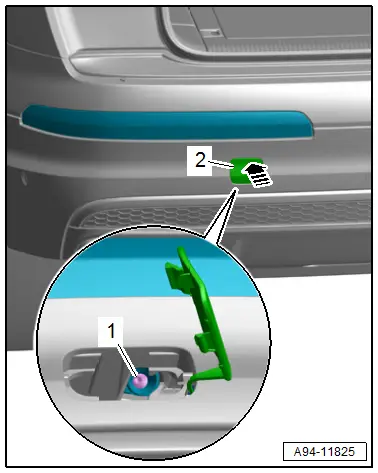
Tail Lamp, Removing and Installing
Removing
- Turn the light switch to position "0".
- To protect the paint in the area around the cap, tape it off with a soft cloth.
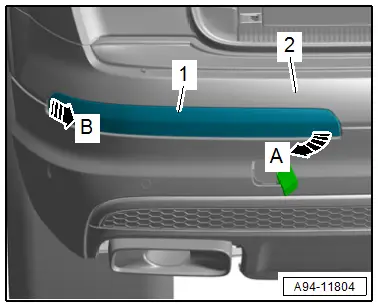
- Push the upper cap -2- on the outside inward in direction of -arrow-.
- Remove the cap and let it hang.
- Remove the bolt -1-.
- Pivot the tail lamp -1- on the inside of the bumper cover -2- slightly outward in direction of -arrow A- and remove from the outside from the bumper cover in direction of -arrow B-.
- Disconnect the connector.
Installing
Install in the reverse order of removal while noting the following:
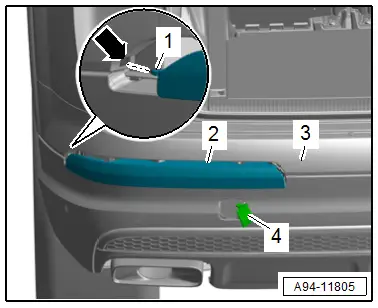
- First insert the tail lamp -2- on the outside in the bumper cover -3-. The guide -1- must engage in the mount -arrow- while doing so.
- Tighten the bolt.
- Push the cap -4- until it engages audibly in the bumper cover.
Tightening Specifications
- Refer to → Chapter "Overview - Body Tail Lamps"
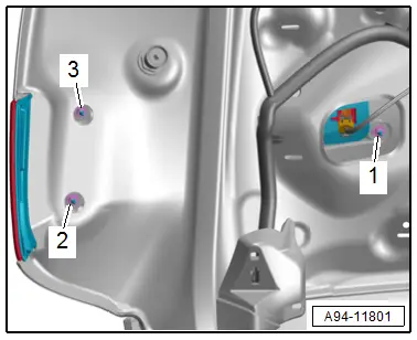
Rear Lid Tail Lamp, Removing and Installing
Removing
- Turn the light switch to position "0".
- Remove the rear lid lower trim panel. Refer to → Body Interior; Rep. Gr.70; Luggage Compartment Trim Panels; Rear Lid Lower Trim Panel, Removing and Installing.
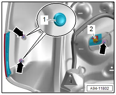
- Disconnect the connector -2-.
- Remove the grommets -1-.
- Remove the nuts -arrows-.
- Remove the tail lamp.
Installing
Install in the reverse order of removal while noting the following:
- Check the self-adhesive seal -1- and spacer -3- on the tail lamp -2- for damage.
- A damaged or incorrectly attached seal must be replaced.
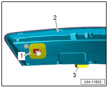
TIP
Water can get into the vehicle interior due to a damaged or incorrectly attached seal.
Tightening Specifications
- Refer to → Fig. "Tightening Specification and Sequence for the Tail Lamps"
Bulb Holder, Removing and Installing
Bumper Cover Tail Lamp Bulbs, Removing and Installing
Removing
- Remove the tail lamp. Refer to → Chapter "Tail Lamp, Removing and Installing".
- Turn the socket -1- counter-clockwise in direction of -arrow- and remove it from the tail lamp.
- Remove the bulb -4- from the bulb socket -3-.
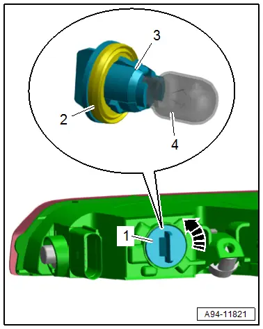
Installing
Install in the reverse order of removal while noting the following:
- Check the seal -2- for damage.
- Insert new bulbs in the bulb socket. Do not touch the bulb glass with bare hands.
- Secure the socket by turning it clockwise.
Rear Lid -Closed- Sensor 1 and 2 -G525-/-G526-, Removing and Installing
Removing
- Remove the lock carrier trim panel. Refer to → Body Interior; Rep. Gr.70; Luggage Compartment Trim Panels; Lock Carrier Trim Panel, Removing and Installing.
- Remove the bolts -2 and 3-.
- Remove the rear lid -closed- sensor -1-.
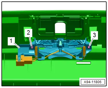
Installing
Install in reverse order of removal.
Tightening Specifications
- Refer to → Chapter "Overview - Body Tail Lamps"

