Audi Q7: Oil Pan/Oil Pump
Overview - Oil Pan/Oil Pump
 Note
Note
- If large quantities of metal shavings or abraded material are detected during engine repairs, it may mean the crankshaft or connecting rod bearings are damaged. To prevent damage, perform the following steps after completing the repair; carefully clean the oil channels and replace the oil spray jets, the oil cooler and the oil filter.
- Oil capacities, oil specifications and viscosity classes. Refer to →Fluid Capacity Tables; Rep. Gr.03
- Oil spray jet for piston cooling. Refer to → Fig. "Oil Spray Jet for Piston Cooling".
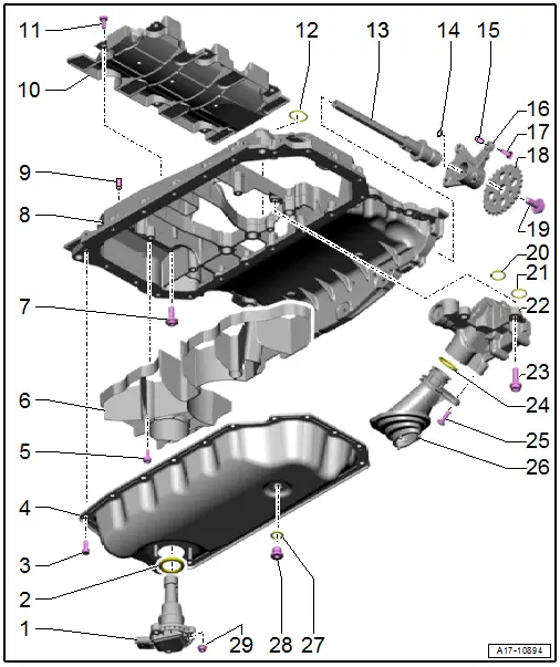
1 - Oil Level Thermal Sensor -G266-
- Removing and installing. Refer to → Chapter "Oil Level Thermal Sensor -G266-, Removing and Installing".
2 - Gasket
- Replace after removing
3 - Bolt
- Replace after removing
- Tightening specification and sequence. Refer to → Fig. "Oil Pan Lower Section - Tightening Specification and Sequence".
4 - Oil Pan Lower Section
- Removing and installing. Refer to → Chapter "Oil Pan Lower Section, Removing and Installing".
5 - Bolt
- 9 Nm
6 - Lower Oil Baffle
7 - Bolt
- Replace after removing
- Tightening specification and sequence. Refer to → Fig. "Oil Pan Upper Section - Tightening Specifications and Sequence".
8 - Oil Pan Upper Section
- Removing and installing. Refer to → Chapter "Oil Pan Upper Section, Removing and Installing".
9 - Alignment Sleeve
- Quantity: 2
10 - Upper Oil Baffle
11 - Bolt
- 3 Nm +90Âş
- Replace after removing
- Install with locking compound. Refer to the Parts Catalog for the locking compound.
12 - Seal
- Insert into guide frame
- Replace after removing
13 - Oil Pump Input Shaft
14 - O-Ring
- Replace after removing
15 - Sleeve
- Quantity: 2
16 - Mounting Bracket
17 - Bolt
- 9 Nm
18 - Chain Sprocket for Oil Pump
- Can only be placed onto drive axle in one position
19 - Bolt
- 3 Nm +90Âş
- Replace after removing
20 - O-Ring
- Replace after removing
21 - Seal
- Replace after removing
22 - Oil Pump
- Do not disassemble
- Removing and installing. Refer to → Chapter "Oil Pump, Removing and Installing".
23 - Bolt
- 20 Nm
24 - O-Ring
- Replace after removing
25 - Bolt
- 9 Nm
26 - Intake Tube
- For the oil pump
27 - Gasket
- Replace after removing
28 - Oil Drain Plug
- 30 Nm
29 - Nut
- 9 Nm
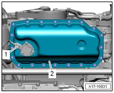
Oil Pan Lower Section - Tightening Specification and Sequence
 Note
Note
Replace the bolts that were tightened with an additional turn after removing them.
- Tighten the bolts in stages as follows:

Oil Pan Upper Section - Tightening Specifications and Sequence
- Then tighten the bolts -1 through 6- in a diagonal sequence in stages to 20 Nm:

Oil Dipstick Tube - Tightening Specification
- Tighten the bolt -arrow- to 9 Nm.
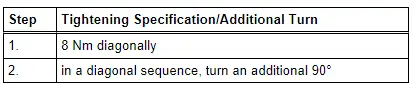
Wiring Harness Bracket - Tightening Specification
- Tighten the bolt -1- to 9 Nm.

Engine Oil
Oil capacities, oil specifications and viscosity classes. Refer to →Fluid Capacity Tables; Rep. Gr.03
 Caution
Danger of catalytic converter damage.
The oil level must not exceed the "MAX" mark.
Oil Pan Lower Section, Removing and Installing
Special tools and workshop equipment required
- Hand Drill with Plastic Brush Attachment
- Protective Eyewear
- Sealant. Refer to the Parts Catalog.
 Caution
This procedure contains mandatory replaceable parts. Refer to component overview prior to starting procedure.
Mandatory Replacement Parts
- Bolts - Oil pan lower section
Removing
- Engine oil drained.
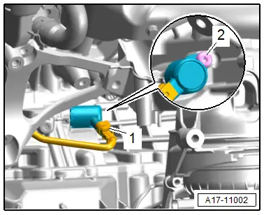
- Remove the bolt -1- and move the bracket -2- and wiring harness to the side.
- Disconnect the electrical connector -1- on the Oil Level Thermal Sensor -G266- and free up the electrical wire.
 Caution
There is a risk of contamination.
There is still a residual amount of oil in the oil pan lower section.
- Loosen oil pan lower section bolts -2- in a diagonal sequence and remove.
- Carefully remove the oil pan lower section from the adhesive for example with a scraper, without bending it.
Installing
 Note
Note
Replace the lower section of the oil pan if the coating on it is damaged or if it is bent.
 Caution
Risk of contaminating the lubricating system and the bearing.
Cover open engine components.
 WARNING
Risk of eye injury.
Wear protective eyewear!
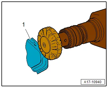
- Remove any sealant residue on the oil pan lower -1- and upper sections using a rotating plastic brush.
- Clean any oil or grease off the sealing surfaces.

 Note
Note
Note the expiration date for the sealant.
- Cut the tube nozzle at the front marking (tube nozzle diameter: approximately 1 mm).
 Caution
There is a risk that the lubrication system could be blocked by excess sealant.
Do not apply sealant bead thicker than indicated.
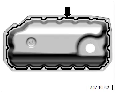
- Apply a sealant bead -arrow- to the clean sealing surface on the lower section of the oil pan as shown.
- Sealant bead thickness is approximately 1.5 mm.
 Note
Note
Install the oil pan lower section within five minutes of applying the sealant.
- Mount the oil pan lower section -2- and tighten the bolt. Refer to → Fig. "Oil Pan Lower Section - Tightening Specification and Sequence" and then connect the connector -1-.
Installation is performed in reverse order of removal, while noting the following:
- Fill with engine oil and check the oil level.

Tightening Specifications
- Refer to → Fig. "Oil Pan Lower Section - Tightening Specification and Sequence"
- Refer to → Fig. "Wiring Harness Bracket - Tightening Specification"
Oil Pan Upper Section, Removing and Installing
Special tools and workshop equipment required
- Protective Eyewear
- Hand Drill with Plastic Brush Attachment
- Sealant. Refer to the Parts Catalog.
 Caution
This procedure contains mandatory replaceable parts. Refer to component overview prior to starting procedure.
Mandatory Replacement Parts
- Bolts - Oil pan upper section
- Seal - Oil pan upper section
Removing
- The engine is secured to the engine and transmission holder. Refer to → Chapter "Engine, Securing to Engine and Transmission Holder".
- Remove the lower timing chain cover. Refer to → Chapter "Lower Timing Chain Cover, Removing and Installing".
- Remove the oil pump. Refer to → Chapter "Oil Pump, Removing and Installing".
- Remove the A/C compressor from the bracket and tie it up toward the front. Refer to → Heating, Ventilation and Air Conditioning; Rep. Gr.87; A/C Compressor; A/C Compressor, Removing and Installing at Bracket.
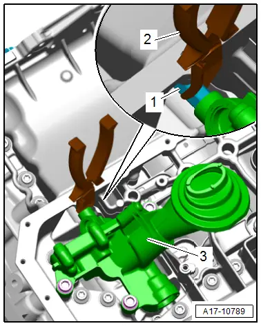
- Disconnect the connector -1- for the Oil Pressure Regulation Valve -N428-.
 Note
Note
Ignore -2-.
- Free up the wiring harness to the Engine Speed Sensor -G28-.
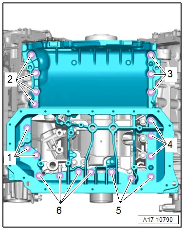
- Loosen and remove the oil pan upper section bolts -1 through 6- in a diagonal sequence.
- Carefully loosen the oil pan upper section from the bond and press it off the cylinder block alignment bushings.
Installing
 Note
Note
Replace the seal and O-ring after removal.
 Caution
Risk of contaminating the lubricating system and the bearing.
Cover open engine components.
- Remove any old sealant from the grooves on the oil pan upper section as well as from the sealing surface.
 WARNING
Risk of eye injury.
Wear protective eyewear!
- Remove sealant residue on the upper section of the oil pan -1- and the cylinder block, for example using a rotating plastic brush.
- Clean any oil or grease off the sealing surfaces.
 Note
Note
Note the expiration date for the sealant.
- Cut the tube nozzle at the front marking (nozzle diameter: approximately 1.5 mm).
 Caution
There is a risk that the lubrication system could be blocked by excess sealant.
Do not apply sealant bead thicker than indicated.
- Apply a sealant bead -arrow- to the clean sealing surface on the upper section of the oil pan as shown in the illustration.
- Completely fill the grooves on the sealing surfaces with sealant.
- The sealant bead must be 1.5 to 2.0 mm above the sealing surface.
 Note
Note
Install the oil pan upper section within five minutes of applying the sealant.
- Insert the seal -1- in the guide frame.
 Note
Note
Ignore -2-.
- Position the oil pan upper section while paying attention to the alignment bushings and tighten the bolts. Refer to → Fig. "Oil Pan Upper Section - Tightening Specifications and Sequence".
Installation is performed in reverse order of removal, while noting the following:
- Install the oil pump. Refer to → Chapter "Oil Pump, Removing and Installing".
- Install the lower timing chain cover. Refer to → Chapter "Lower Timing Chain Cover, Removing and Installing".

Tightening Specifications
- Refer to → Chapter "Overview - Oil Pan/Oil Pump"
- Refer to → Fig. "Oil Pan Upper Section - Tightening Specifications and Sequence"
- Refer to → Heating, Ventilation and Air Conditioning; Rep. Gr.87; A/C Compressor; Overview - A/C Compressor Power Unit.
Oil Pump, Removing and Installing
Removing
 Caution
This procedure contains mandatory replaceable parts. Refer to component overview prior to starting procedure.
Mandatory Replacement Parts
- O-rings - Oil pump
- Remove the oil pan lower section. Refer to → Chapter "Oil Pan Lower Section, Removing and Installing".
- Remove the bolts -arrows- and remove the oil baffle.
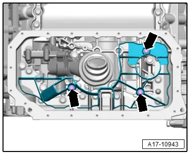
- Remove the bolts -arrows-.
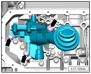
- Push the drive axle -1- with pliers -2- against the spring force and remove the oil pump -3-.
 Note
Note
The oil pump input shaft remains installed.
Installing
Install in reverse order of removal and note the following:
 Note
Note
Replace the O-rings after removing them.
- Install the oil pan lower section. Refer to → Chapter "Oil Pan Lower Section, Removing and Installing".
- Fill with engine oil and check the oil level.
Tightening Specifications
- Refer to → Chapter "Overview - Oil Pan/Oil Pump"
Oil Level Thermal Sensor -G266-, Removing and Installing
 Caution
This procedure contains mandatory replaceable parts. Refer to component overview prior to starting procedure.
Mandatory Replacement Parts
- Gasket - Oil level thermal sensor
Removing
- Engine oil drained.
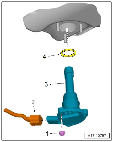
- Disconnect the connector -2-.
- Remove the nuts -1- and the Oil Level Thermal Sensor -G266--3-.
Installing
Install in reverse order of removal and note the following:
 Note
Note
Replace the seal -4- after removal.
- Fill with engine oil and check the oil level.
Tightening Specifications
- Refer to → Chapter "Overview - Oil Pan/Oil Pump"

