Audi Q7: Valvetrain
Overview - Valvetrain
 Note
Note
- Cylinder heads with cracks between the valve seats or between valve seat ring and spark plug thread can still be used without loss of service life if the cracks are minute (max. 0.3 mm width) or only the first four threads of a spark plug thread are cracked.
- The cylinder head for cylinder bank 2 (left) is shown in the illustration.
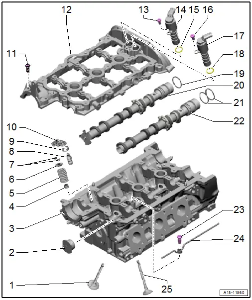
1 - Exhaust Valve
- Do not rework, only lapping is permitted
- Mark the installed position for reinstallation.
- Checking using the Vehicle Diagnostic Tester. Refer to → Chapter "Valves, Checking".
- Valve Dimensions. Refer to → Chapter "Valve Dimensions".
- Valve Guides, Checking. Refer to → Chapter "Valve Guides, Checking".
2 - Plugs
- Install with sealant. Refer to the Parts Catalog.
3 - Cylinder Head
- Valve Guides, Checking. Refer to → Chapter "Valve Guides, Checking".
4 - Valve Stem Seal
- Removing and installing. Refer to → Chapter "Valve Stem Seals, Removing and Installing".
5 - Valve Spring
- Installation position. Refer to → Fig. "Installed Position, Valve Spring".
6 - Valve Spring Retainer
7 - Valve Retainers
8 - Hydraulic Lifter
- Clipped into roller rocker lever -item 8-
- Checking using the Vehicle Diagnostic Tester. Refer to → Chapter "Hydraulic Lifter, Checking".
- Mark the installed position for reinstallation.
- Lubricate the running surfaces before installing
9 - Clip
- Not available separately.
- Check for secure fit
10 - Roller Rocker Lever
- Mark the installed position for reinstallation.
- Check the roller bearing for ease of movement
- Lubricate the running surfaces before installing
- To assemble, clip onto the hydraulic lifter -item 9- with clip -item 5-
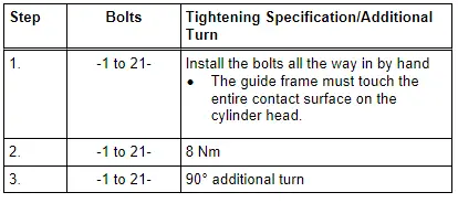
11 - Bolt
- Replace after removing
- Tightening specification and sequence. Refer to → Fig. "Guide Frame for the Camshaft Cylinder Head Bank 2 (Left) - Tightening Specification and Sequence".
12 - Guide Frame
- With integrated camshaft bearings
- Removing and installing. Refer to → Chapter "Camshaft, Removing and Installing".
13 - Bolt
- 5 Nm
14 - Camshaft Adjustment Valve 2 -N208-
- Cylinder bank 1 (right) Camshaft Adjustment Valve 1 -N205-
- Removing and installing. Refer to → Chapter "Camshaft Adjuster Valves, Removing and Installing".
15 - O-Ring
- Replace after removing
16 - Bolt
- 5 Nm
17 - Exhaust Camshaft Adjustment Valve 2 -N319-
- Cylinder bank 1 (right) Exhaust Camshaft Control Valve 1 -N318-
- Removing and installing. Refer to → Chapter "Camshaft Adjuster Valves, Removing and Installing".
18 - O-Ring
- Replace after removing
19 - Flat Ring
20 - Intake Camshaft
- Removing and installing. Refer to → Chapter "Camshaft, Removing and Installing".
- Axial play, measuring. Refer to → Chapter "Camshaft, Measuring Axial Clearance".
- Radial play, measuring. Refer to → Chapter "Camshaft, Measuring Radial Clearance".
- Maximum run out: 0.04 mm
21 - Compression Rings
- Depending on the version one or two are installed. Refer to the Parts Catalog for the allocation.
22 - Exhaust Camshaft
- Removing and installing. Refer to → Chapter "Camshaft, Removing and Installing".
- Axial play, measuring. Refer to → Chapter "Camshaft, Measuring Axial Clearance".
- Radial play, measuring. Refer to → Chapter "Camshaft, Measuring Radial Clearance".
- Maximum run out: 0.04 mm
23 - Banjo Bolt
- 25 Nm
- With valve
24 - Oil Pipe
25 - Intake Valve
- Do not rework, only lapping is permitted
- Mark the installed position for reinstallation.
- Checking using the Vehicle Diagnostic Tester. Refer to → Chapter "Valves, Checking".
- Valve Dimensions. Refer to → Chapter "Valve Dimensions".
- Valve Guides, Checking. Refer to → Chapter "Valve Guides, Checking".
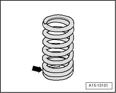
Installed Position, Valve Spring
- The tight spring coils -arrow- face toward the cylinder head.
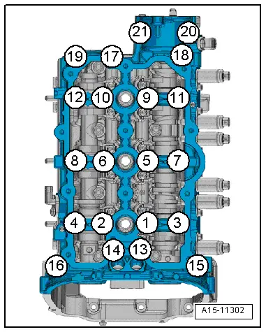
Guide Frame for the Camshaft Cylinder Head Bank 1 (Right) - Tightening Specification and Sequence
 Note
Note
Replace the bolts that were tightened with an additional turn after removing them.
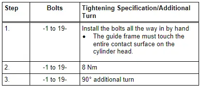
- Tighten the bolts in the steps of the sequence shown:
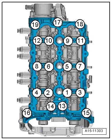
Guide Frame for the Camshaft Cylinder Head Bank 2 (Left) - Tightening Specification and Sequence
 Note
Note
Replace the bolts that were tightened with an additional turn after removing them.
- Tighten the bolts in the steps of the sequence shown: