Audi Q7: A/C Compressor, Removing and Installing
Information on the Mechanically Driven A/C Compressor
 Note
Note
- At the start of production, the A/C compressors manufactured by "Denso" (type "6 SEU 14") are installed. A/C compressors from other manufacturers or another type may also be installed at a later time. Refer to the Parts Catalog and → A/C system - with refrigerant R134a; Rep. Gr.87; A/C System, General Information.
- Depending on the time period of production and the engine, the compressor construction type may vary. Refer to the Parts Catalog.
- Depending on the vehicle version, the production time period and the engine, the A/C Compressor can be installed with or without the A/C Clutch -N25-.
- The A/C compressor without an A/C Clutch -N25- is always driven when the engine is running. Since the version of the A/C Compressor (with or without the A/C Clutch -N25-) above is not always clearly distinguished, the engine may only be started when the refrigerant circuit has been properly assembled. If, for example, the refrigerant lines are not connected to the A/C compressor and the engine is started and runs, then the A/C compressor may be destroyed by the build-up of internal heat. Such internal heat generation results from the fact that - even with delivery near 0% - the A/C compressor is confronted with a fixed resistance (sealed circuit).
- To stop the A/C compressor being destroyed when the refrigerant circuit is empty, it is designed such that delivery is reduced to roughly 0% and lubrication is maintained by way of an internal oil circuit with the oil left in the A/C compressor.
- These A/C compressors are available as replacement parts with different oil fill capacities, therefore note the capacity on the A/C compressor. Refer to → Refrigerant R134a Servicing; Rep. Gr.87; Refrigerant R134a Capacities, Refrigerant Oil and Approved Refrigerant Oils and the exact part number. Refer to the Parts Catalog.
- Depending on A/C compressor type, different refrigerant oil capacities are designated for the refrigerant circuit. The reason for the different oil capacities in the A/C compressor for an otherwise identical refrigerant circuit lies in the design of the A/C compressor itself, note these oil capacities. Too much oil in the circuit leads to higher pressures and reduces cooling performance of the system. Too little oil may lead to lubrication problems in the compressor. Refer to →Maintenance Intervals; Rep. Gr.03.
- If a new compressor has been installed or new refrigerant oil has been put into the A/C compressor (for example, after flushing refrigerant circuit), the A/C compressor must be turned by hand approximately 10 revolutions. This ensures that the A/C compressor is not damaged when activated. Refer to → Refrigerant R134a Servicing; Rep. Gr.87; Refrigerant Circuit Components, Replacing.
A/C Compressor, Removing and Installing, Vehicles with 6-Cylinder Engine
 Caution
This procedure contains mandatory replaceable parts. Refer to component overview prior to starting procedure.
Mandatory Replacement Parts
- O-ring - Low Pressure Side Refrigerant Line to A/C Compressor
- O-ring - High Pressure Side Refrigerant Line to A/C Compressor
Removing
- Remove the refrigerant lines from the A/C compressor. Refer to → Chapter "Refrigerant Lines, Disconnecting and Connecting at A/C Compressor, Vehicles with 6-Cylinder Engine".
- Remove the A/C compressor.
Installing
Install in reverse order of removal. Note the following:
 Note
Note
There is an unspecified amount of refrigerant oil in the removed compressor, so follow the information on replacing the compressor. Refer to → A/C System with Refrigerant R134a; Rep. Gr.87; A/C System, General Information.
Before installing A/C compressor. Refer to → Refrigerant R134a Servicing; Rep. Gr.87; A/C System, General Information.
- Attach the refrigerant lines to the A/C compressor. Refer to → Chapter "Refrigerant Lines, Disconnecting and Connecting at A/C Compressor, Vehicles with 6-Cylinder Engine".
 Note
Note
Coat the O-ring seals lightly with refrigerant oil prior to installation. Refer to → Chapter "Refrigerant Circuit Seals".
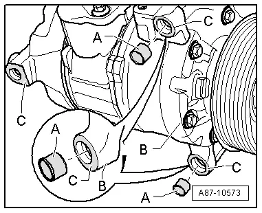
- Before tightening the A/C compressor, check seating of both alignment bushings -A- in bracket or A/C compressor -B-.
 Note
Note
- The alignment sleeves -A- have different styles (different lengths), make sure to use the correct style. Refer to the Parts Catalog.
- Ensure bushings -A- are properly seated and contact surfaces are clean. Incorrectly installed bushings and dirty or damaged contact surfaces -C- on the bracket or A/C compressor can lead to alignment irregularities between the A/C compressor and engine. Alignment irregularities over operating time lead to damage to the ribbed belt or A/C compressor.
- Turn the A/C compressor by hand 10 rotations before installing the ribbed belt on the pulley (to prevent damage to the compressor when it is first switched on).
 Note
Note
- Rotating can prevent damage to the A/C compressor if there is refrigerant oil in the compression chamber when the engine is started for the first time.
- After fastening the A/C compressor and installing the refrigerant line, check installation position of refrigerant lines, lines must be engaged in bracket (if installed, depending on engine).
- Check refrigerant lines and their bracket to ensure there is enough distance to the other components. Ensure there is also enough distance between belts, bracket and pulley.
- Evacuate and charge the refrigerant circuit. Refer to → Refrigerant R134a Servicing; Rep. Gr.87; Refrigerant Circuit.
- Install the remaining removed components.
- Turn on the ignition.
- Retrieve the Front A/C Display Control Head -E87- DTC memory and if necessary delete the displayed error. Refer to Vehicle Diagnostic Tester in the "Guided Fault Finding" function.
- Operate the A/C system after charging the refrigerant circuit. Refer to → Chapter "A/C System, Starting after Charging Refrigerant Circuit".
 Note
Note
Note the information regarding operating the A/C system after filling. Refer to → Refrigerant R134a Servicing; Rep. Gr.87; A/C System, General Information.
Preliminary Work for Replacing Belt Pulley
 Note
Note
It is possible to remove and reinstall the A/C compressor on the bracket for vehicles with a 4- or 6- cylinder TFSI or FSI engine, a 6-cylinder TDI engine or an 8-cylinder TDI engine without having to open the refrigerant lines.
- Turn off the ignition.
- Remove the front noise insulation. Refer to → Body Exterior; Rep. Gr.66; Noise Insulation; Noise Insulation, Removing and Installing.
- Remove the ribbed belt from the A/C compressor belt pulley. Refer to → Rep. Gr.13; Cylinder Block, Belt Pulley Side; Ribbed Belt, Removing and Installing.
- If necessary, remove the A/C compressor from the bracket and tilt the front downward.
- Refer to → Chapter "A/C Compressor, Removing and Installing on Bracket, Vehicles with 4-Cylinder TFSI Engine"
- Refer to → Chapter "A/C Compressor, Removing from and Installing on Bracket, Vehicles with 6-Cylinder Engine"
- Refer to → Chapter "A/C Compressor, Removing and Installing on Bracket, Vehicles with 8-Cylinder TDI Engine"
 Note
Note
- There is an overload protection installed between the belt pulley and the A/C compressor input shaft to protect the belt should the A/C compressor get blocked or be difficult to move.
- If the A/C compressor runs with resistance, the overload safeguard interrupts the supply of power to it.
- Rubber elements are installed between belt pulley and A/C compressor drive axle, vibrations which may occur during A/C compressor operation may be dissipated via these rubber elements (damper function at torque fluctuations).
- There are different versions of the pulley are installed depending on the type of A/C compressor and engine. Refer to the Parts Catalog and → Chapter "Overview - Belt Pulley".

