Audi Q7: Belt Pulley, Removing and Installing
Belt Pulley (without A/C Clutch -N25-) Removing and Installing, "Denso" Version "1"
 Caution
This procedure contains mandatory replaceable parts. Refer to component overview prior to starting procedure.
Mandatory Replacement Parts
- Circlip - for A/C Compressor
- Drive Plate for A/C Compressor
 Note
Note
- Observe notes on replacing belt pulley -E-. Refer to → Chapter "Overview - A/C Compressor Belt Pulley, Denso Version 1".
- Perform preparatory work as for removing belt pulley. Refer to → Chapter "Preliminary Work for Replacing Belt Pulley".
- The belt pulley is made of plastic and is sensitive to impact, therefore take special care when handling it.
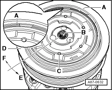
- If the drive plate -C- overload protection activates, rotate the pulley -E- using the outer part of the drive plate -C- so that the compressor shaft -B- and the hexagon head on the drive plate -D- (inner part of the drive plate -C-) do not rotate.
- Perform the preparatory work. Refer to → Chapter "Preliminary Work for Replacing Belt Pulley".

Removing
- Remove the cap -A-.
- Hold the A/C compressor input shaft -B- with a 7 mm wrench and turn the drive plate -C- together with the pulley -E- in the direction of -arrow-.
 Note
Note
The torque to drive the A/C compressor is transferred to the drive plate -C- via the threaded connection. If, while the A/C compressor is working, the drive plate -C- was attached to the A/C compressor shaft so tight, that it cannot be loosened (the 7 mm Allen wrench -B- cannot transmit the necessary torque) then the A/C compressor must be replaced.
- Remove the drive plate -C- .

- Remove the circlip -A-.
- Remove the pulley -B- .
Installing
 Note
Note
Replace circlip -A-.
Clean A/C compressor flange before installing pulley -B-.
When installing circlip -A-, note that it cannot be bent open more than is necessary for installation.
- Install the pulley -B- .
- Insert circlip -A- on correct side, the side with beveled insertion edge -C- faces away from A/C compressor (install flat side facing A/C compressor).
- Clean the compressor shaft thread.
 Note
Note
The threads of the new drive plate has already been greased with a specific amount of a grease by the manufacturer.
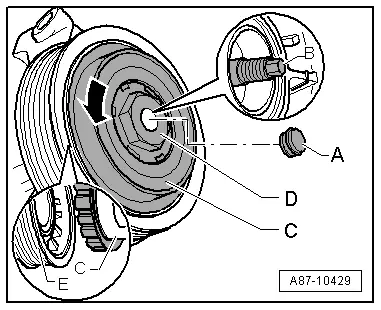
- When installing drive plate, coat the rubber element -D- lightly, for example, with tire mounting paste or soap solution (as sliding compound).
- Insert rubber element -D- in belt pulley -B- according to illustration.
- Press the drive plate rubber element -C- far enough into the belt pulley -E- until the drive plate -C- contacts the A/C compressor shaft threads -B- .
- Attach the drive plate -C- to the compressor shaft -B- by turning it contrary to the direction of the -arrow-.
- Hold the A/C compressor input shaft -B- for example, with a standard 7 mm Allen wrench and turn the drive plate -C- together with the belt pulley -E- opposite the direction of the -arrow- (tightening specification 30 Nm).
Belt Pulley (without A/C Clutch -N25-), Removing and Installing, "Denso" A/C Compressor Version "2"
 Caution
This procedure contains mandatory replaceable parts. Refer to component overview prior to starting procedure.
Mandatory Replacement Parts
- Circlip - to A/C Compressor
 Note
Note
- Follow the instructions for replacing the belt pulley. Refer to → Chapter "Overview - A/C Compressor Belt Pulley, Denso Version 2".
- The belt pulley is made of plastic and is sensitive to impact, therefore take special care when handling it.
- If overload safeguard of drive plate -C- has triggered, drive plate can be pried off from belt pulley -D- after removing circlip -A-
- To optimize noise reduction, a circlip -A- with a rubber disc vulcanized on it is installed. Refer to → Chapter "Overview - A/C Compressor Belt Pulley, Denso Version 2" and the Parts Catalog.
Removing
- Perform the preparatory work. Refer to → Chapter "Preliminary Work for Replacing Belt Pulley".
- Remove the ribbed belt. Refer to → Rep. Gr.13; Cylinder Block, Belt Pulley Side; Ribbed Belt, Removing and Installing.

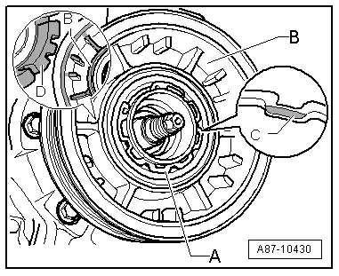
- Using, for example, a small screwdriver or needle-nose pliers, carefully remove the circlip -A- with rubber disc vulcanized onto it. Refer to → Chapter "Overview - A/C Compressor Belt Pulley, Denso Version 2". Take extreme care not to damage belt pulley when doing this.
- Hold the A/C compressor input shaft -B- securely with a standard socket wrench and turn drive plate -C- with pulley -D- in direction of -arrow E- (tightening specification 35 Nm).
- Remove the drive plate -C-.

- Remove the circlip -A-.
- Remove the belt pulley -B-.
 Note
Note
Do not remove the belt pulley from an installed A/C compressor. Remove the A/C compressor with the refrigerant lines connected: For a 4 cylinder engine. Refer to → Chapter "A/C Compressor, Removing and Installing on Bracket, Vehicles with 4-Cylinder TFSI Engine". For a 6-cylinder TDI-engine. Refer to → Chapter "A/C Compressor, Removing from and Installing on Bracket, Vehicles with 6-Cylinder Engine". The A/C compressor must be removed on vehicles with a 6-cylinder FSI/TFSI engine. Refer to → Chapter "A/C Compressor, Removing and Installing, Vehicles with 6-Cylinder Engine".
Installing
 Note
Note
Replace circlip -A-.
Clean the A/C compressor flange before sliding on the belt pulley.
When installing the circlip -A-, note that it cannot be bent open more than is necessary for installation.
- Install the belt pulley -B-.
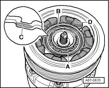
- Insert circlip -A- on correct side, the side with beveled insertion edge -C- faces away from A/C compressor (install flat side facing compressor).
- Insert rubber element -D- in belt pulley -B- according to illustration.
- When installing drive plate, coat rubber element -D- lightly for example with tire mounting paste or soap solution (as sliding compound).

- Insert the drive plate -C- far enough into rubber elements -D- (see upper illustration) until it contacts A/C compressor shaft -B-.
- Install the drive plate -C- on the compressor shaft -B- by rotating it in the direction of the arrow -F-.
- Tighten drive plate -C- (above pulley -D-) to 35 Nm by turning with a standard band wrench (with webbing) in direction of -arrow F-, hold compressor shaft -B- with a standard socket wrench.
- Install circlip -A- (with rubber disc vulcanized on).

Belt Pulley (without A/C Clutch -N25-) Removing and Installing, Sanden A/C Compressor
 Note
Note
- Belt pulley is sensitive to impact. Handle it with special care
- If the belt pulley overload protection was activated, check the A/C compressor for ease of movement before replacing the belt pulley. Replace an A/C compressor that is not operating smoothly.
- If the drive plate overload protection was activated, the belt pulley can be rotated using the outer part of the drive plate so that the A/C compressor shaft and the hex fitting on the drive plate (inner part of the drive plate) do not rotate.
- Remove the ribbed belt. Refer to → Rep. Gr.13; Cylinder Block, Belt Pulley Side; Ribbed Belt, Removing and Installing.
- Belt pulley, removing and installing. Refer to → Chapter "Overview - Belt Pulley, Sanden A/C Compressor".
Belt Pulley with A/C Clutch -N25-, Removing and Installing
Belt Pulley, Notes with A/C Clutch -N25-
 Note
Note
- If overload protection of pulley triggers, check the A/C compressor for ease of motion before replacing the pulley. If the A/C compressor creates friction, replace it completely.
- In most cases it is not necessary to loosen the A/C compressor from the engine to remove the drive plate. Depending on the engine type, it may be necessary to loosen the lock carrier from the vehicle and to pull it slightly forward (to make space). Refer to → Body Exterior; Rep. Gr.50; Lock Carrier; Lock Carrier, Removing and Installing.
- If the belt pulley cannot be removed with the A/C compressor installed depending on the vehicle and engine, remove the A/C compressor with the refrigerant lines connected. Refer to → Chapter "Preliminary Work for Replacing Belt Pulley".
- Different versions of the belt pulley (with different diameters) may be installed, depending on A/C compressor construction type and engine version. Refer to the Parts Catalog.
- The replacement belt pulley with A/C clutch has a single part number. The belt pulley and the drive plate are held together with one bolt (when the bolt is no longer needed, dispose of it). When the bolt was manufactured, a predetermined amount of a specific grease was applied to the threads in the drive plate; this amount is sufficient for bolting the drive plate to the compressor one time (a drive plate, which has been removed, cannot be reused). Refer to the Parts Catalog.
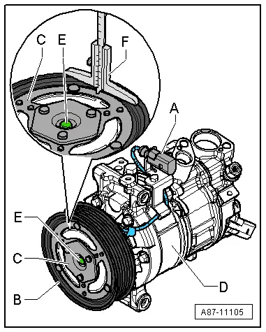
- The following image shows an A/C compressor with a particular connector for activating the A/C Clutch -N25- (a specific connector is equipped on this A/C compressor for activating the A/C Compressor Regulator Valve -N280-. For another A/C compressor version , the wires to activate the A/C Clutch -N25- and the A/C Compressor Regulator Valve -N280- are combined in a 3-pin connector. If necessary, discard the line to the A/C Clutch -N25- using a suitable release tool from the Wiring Harness Repair Set -VAS1978B- from the connector. Refer to → Electrical Equipment General Information; Rep. Gr.97; Wiring Harness and Connector Repairs; Fiber-Optic Cables, Repairing.
Clutch Plate, Removing and Installing
 Caution
This procedure contains mandatory replaceable parts. Refer to component overview prior to starting procedure.
Mandatory Replacement Parts
- Clutch Plate to A/C Compressor
Procedure
- Turn off the ignition.
- Perform the preparatory work. Refer to → Chapter "Preliminary Work for Replacing Belt Pulley".
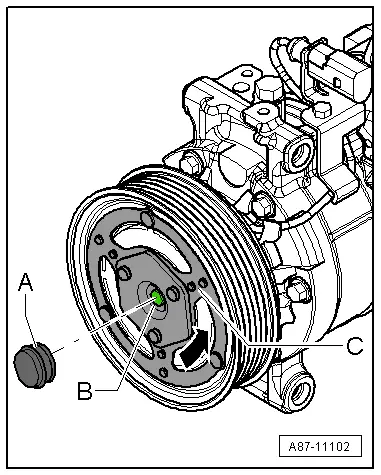
- Remove the cap -A-.
- Hold the A/C compressor input shaft -B- secure with a commercially available socket (7 mm) and turn the clutch plate -C- in direction of -arrow-.
 Note
Note
The torque to drive the A/C compressor is transferred to the clutch plate -C- via the threaded connection. If, while the A/C compressor is working, the clutch plate -C- was attached to the A/C compressor shaft so tight, that it cannot be loosened (the 7 mm Allen wrench -B- cannot transmit the necessary torque) then the A/C compressor must be replaced.
Belt Pulley, Removing
 Note
Note
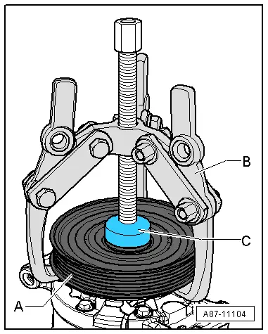
- If the belt pulley -A- (after removing the circlip) cannot be removed from the A/C compressor flange by hand (for example because of debris), carefully remove the belt pulley as described below.
- Mount the arms on the puller so that the outside of the belt pulley does not get bent if the belt pulley -A- is going to be used again.
- Remove the belt pulley -A- with a 3-arm puller -B-.
 Note
Note
- Do not support the puller spindle -B- on the A/C compressor shaft when removing the belt pulley -A-.
- Use a sleeve -C- (for example, A/C Clutch Set - Sleeve -VAG1719/1-taken from A/C Clutch Set -VAG1719-) to support the spindle on the arm puller -B- on the A/C compressor flange.
- Clean the flange on the A/C compressor thoroughly after removing the belt pulley -A-. It must possible to install the belt pulley -A- by hand.
Gap Dimension Between Belt and Clutch Plate, Checking
 Note
Note
- The gap dimension must be within the permissible range over the entire circumference.
- Gap dimension may also be measured with A/C compressor installed.
- If the gap dimension is outside of the permissible range, first remove the clutch plate and then remove or insert spacers to get to attain the correct dimension.
Procedure
- Tighten the clutch plate -C- on the A/C compressor shaft -E- to 30 Nm. Refer to → Chapter "Clutch Plate, Removing and Installing".
- Measure the dimension "1" between the belt pulley -B- and the clutch plate -C- with a depth gauge -F- at three places on the clutch plate -C- circumference and then write down the measured values.
- Apply 12 volts to the wire leading to the solenoid coil in the connector -A-.
 Note
Note
- Depending on the A/C compressor version, the connector -A- can be designed as a 1-pin or 3-pin connector. On a 3-pin connector, both wires to the A/C Compressor Regulator Valve -N280- are also housed in this connector.
- There are different versions of the connector -A-. This illustration shows an A/C compressor on which the solenoid coil and the A/C Compressor Regulator Valve -N280- are connected to the vehicle wiring harness via two connectors.
- Connect the ground to the compressor housing -D-.
- Measure the dimension "2" between the belt pulley -B- and the clutch plate -C- with a depth gauge -F- at three places on the clutch plate -C- circumference and then write down the measured values.
- Calculate the gap dimension using dimensions "1" and "2".
Specified value for gap dimension: 0.4 to 0.6 mm (up to 0.8 mm on a previously used A/C clutch).