Audi Q7: A/C Compressor, Removing and Installing at Bracket
A/C Compressor, Removing from and Installing on Bracket, Vehicles with 6-Cylinder Engine
 Caution
This procedure contains mandatory replaceable parts. Refer to component overview prior to starting procedure.
Mandatory Replacement Parts
- O-ring - Low Pressure Side Refrigerant Line to A/C Compressor
- O-ring - High Pressure Side Refrigerant Line to A/C Compressor
- Bolts - A/C Compressor to Sub-Assembly Bracket (Aluminum Bolt)
 Note
Note
- The A/C compressor can be removed and installed at the bracket without opening the refrigerant lines.
- Do not discharge the refrigerant circuit to remove the bracket, do not remove refrigerant hoses and lines from A/C compressor.
- Do not unfasten refrigerant lines and corresponding clamps.
- After removing the A/C compressor, tie it to the vehicle with wire. Do not let is hang by the refrigerant lines.
- Before removing, mark direction of operation of ribbed belt with chalk or felt-tipped pen. Running a used belt in the opposite direction could destroy it.
- Different A/C compressors may be installed depending on the engine and country. Refer to the Parts Catalog.
Removing
- Turn off the ignition.
- Remove the front noise insulation. Refer to → Body Exterior; Rep. Gr.66; Noise Insulation; Noise Insulation, Removing and Installing.
- Remove the lower left longitudinal member. Refer to → Body Exterior; Rep. Gr.50; Lock Carrier; Overview - Lock Carrier.
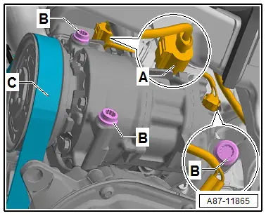
- Remove the ribbed belt -C- from the A/C compressor belt pulley. Refer to → Rep. Gr.13; Cylinder Block, Belt Pulley Side; Ribbed Belt, Removing and Installing.
- Disconnect the connector -A-.
- Remove the A/C compressor bolt -B-.
- Remove the A/C compressor and move it away from the engine only so far without bending or pulling the refrigerant hoses.
- Fasten the A/C compressor to the vehicle (for example, with a wire) without pulling or bending the refrigerant pipes.
 Caution
Risk of damaging refrigerant lines and hoses.
Do not stretch, kink or bend refrigerant lines and hoses.
 Note
Note
If the A/C compressor cannot be swiveled away enough from the engine, then the A/C compressor must be removed. Refer to → Chapter "A/C Compressor, Removing and Installing, Vehicles with 6-Cylinder Engine".
Installing
Installation is done is reverse order, observe the following:
- Before tightening the A/C compressor, check seating of both alignment bushings -A- in bracket or A/C compressor -B-.
 Note
Note
- The alignment sleeves -A- have different styles (different lengths), make sure to use the correct style. Refer to the Parts Catalog.
- Ensure bushings -A- are properly seated and contact surfaces are clean. Incorrectly installed bushings and dirty or damaged contact surfaces -C- on the bracket or A/C compressor can lead to alignment irregularities between the A/C compressor and engine. Alignment irregularities over operating time lead to damage to the ribbed belt or A/C compressor.
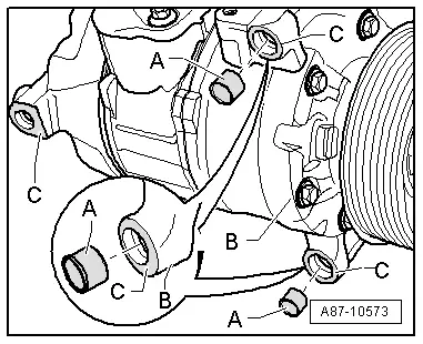
- Tighten the bolts -B-.
- Tightening specification: 25 Nm (steel bolts).
 Note
Note
If the A/C compressor is secured with aluminum bolts (There are different versions. Refer to the Parts Catalog), use the aluminum bolts only once, then replace. Aluminum bolt tightening specification: 8 Nm + 180º.
- Connect the connector -A- on the A/C Compressor Regulator Valve -N280-.
- Mount the ribbed belt -C- on the ribbed belt pulley. Refer to → Rep. Gr.13; Cylinder Block, Belt Pulley Side; Ribbed Belt, Removing and Installing.
 Note
Note
- After fastening the A/C compressor, check installation position of refrigerant lines, lines must be engaged in bracket (if installed, depending on engine).
- Check refrigerant lines and their bracket to ensure there is enough distance to the other components. Ensure there is also enough distance between belts, bracket and pulley.
- Retrieve the Front A/C Display Control Head -E87- DTC memory and if necessary delete the displayed error. Refer to Vehicle Diagnostic Tester in the "Guided Fault Finding" function.

Refrigerant Lines, Disconnecting and Connecting at A/C Compressor
Refrigerant Lines, Disconnecting and Connecting at A/C Compressor, Vehicles with 6-Cylinder Engine
 Caution
This procedure contains mandatory replaceable parts. Refer to component overview prior to starting procedure.
Mandatory Replacement Parts
- O-ring - Low Pressure Side Refrigerant Line to A/C Compressor
- O-ring - High Pressure Side Refrigerant Line to A/C Compressor
 Note
Note
The following procedure describes removing and connecting of the refrigerant lines on a vehicle equipped with a 6 cylinder TDI engine. Vehicles with a 6-cylinder FSI engine may have a few differences, but the refrigerant lines are removed and installed in the same way.
Removing
- Turn off the ignition.
- Discharge the refrigerant circuit. Refer to → Refrigerant R134a Servicing; Rep. Gr.87; Refrigerant Circuit.
- Remove the A/C compressor from the bracket. Refer to → Chapter "A/C Compressor, Removing from and Installing on Bracket, Vehicles with 6-Cylinder Engine".
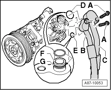
- Remove the bolts -A- and remove the refrigerant lines -B and C-.
 Caution
Risk of damaging refrigerant lines and hoses.
Do not stretch, kink or bend refrigerant lines and hoses.
 Note
Note
Immediately seal off any open line connections and connection points with clean plugs, for example, taken from the Engine Bung Set -VAS6122-.

Installing
Installation is done is reverse order, observe the following:
- Replace the O-rings. Refer to the Parts Catalog for the version.
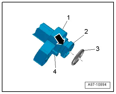
- If equipped, check the alignment pin -4- for damage and proper seating.
- Check the guide ring -2- on the refrigerant line connection for damage.
- Insert the O-ring -3- into the groove -arrow- on the refrigerant line connection -1-.
 Note
Note
- Do not use the O-rings from the closure caps for the replacement A/C compressor connections.
- Coat O-ring seals lightly with refrigerant oil before installing. Refer to → Chapter "Refrigerant Circuit Seals".
- Ensure the proper seating of the O-ring seals in the groove -arrow- of respective refrigerant line.
- After securing the refrigerant lines to the A/C compressor (and installing the A/C compressor), check the line routing. They must be inserted into their designated brackets and cannot make contact with other components.
- Insert the refrigerant lines -B and C- into the respective connection on the A/C compressor.
- Tighten the bolts -A-.
Tightening Specifications
- Bolts -A- to 9 Nm (bolts with a M6 thread) and to 25 Nm (bolts with a M8 thread).
- Install the remaining removed components.
- Evacuate and charge the refrigerant circuit. Refer to → Refrigerant R134a Servicing; Rep. Gr.87; Refrigerant Circuit.
- Operate the A/C system after charging the refrigerant circuit. Refer to → Chapter "A/C System, Starting after Charging Refrigerant Circuit".
After completing the repair work, perform the following operations on the control head. Refer to Vehicle Diagnostic Tester in the "Guided Fault Finding" function:
- Retrieve the Front A/C Display Control Head -E87- DTC memory and delete the displayed error if necessary.
Operate the A/C system after charging the refrigerant circuit. Refer to → Chapter "A/C System, Starting after Charging Refrigerant Circuit".
 Note
Note
Note the information regarding operating the A/C system after filling. Refer to → Refrigerant R134a Servicing; Rep. Gr.87; A/C System, General Information.

