Audi Q7: Air Intake Housing from Heater and A/C Unit, Removing and Installing
- Turn off the ignition.
- Discharge the refrigerant circuit. Refer to → Refrigerant R134a Servicing; Rep. Gr.87; Refrigerant Circuit.
- Remove the front heater and A/C unit. Refer to → Chapter "Heater and A/C Unit, Removing and Installing".
Removing
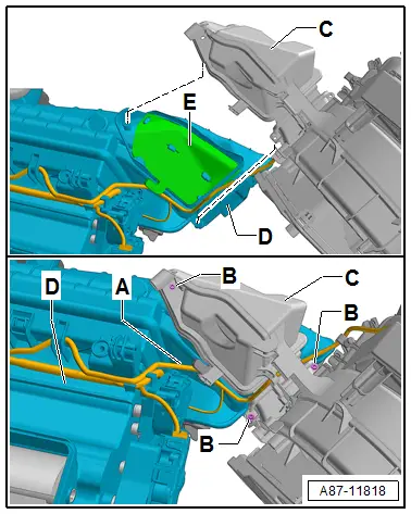
- Remove the acoustic cover and insulation from the air intake housing -C-. Refer to → Chapter "Overview - Heater and A/C Unit"
- Mark the connector and the adjustment motors on the air intake housing and remove. Refer to → Chapter "Overview - Actuators on Air Intake Housing".
- Mark the routing of the wiring harness -A- on the air intake housing -C- (or for example take a picture) and remove from the air intake housing. Refer to → Chapter "Overview - Front Heater and A/C Unit".
- Remove the bolts -B- (tightening specification 1 Nm).
- Disconnect the air intake housing -C- from the heater and A/C unit evaporator housing -D-. Refer to → Chapter "Overview - Front Heater and A/C Unit".
Installing
Reinstall in reverse order of removal. Note the following:
- Check the insulation -E- in the evaporator housing -D- of the heater and A/C unit for damage, contamination (odor) and the correct installation.
- Check the connection points between the air intake housing -C- the evaporator housing -D- from the heater and A/C unit (groove/spring connection) for damage and coat the connection points lightly for example with silicone grease. Refer to → Chapter "Overview - Front Heater and A/C Unit".
- Perform the basic setting and the output diagnostic test mode of the A/C system. Refer to Vehicle Diagnostic Tester in the "Guided Fault Finding" function.
 Note
Note
- In this vehicle, the actuators are equipped with electronics. During the basic setting, a new control motor learns its position on the heater and A/C unit and can then be activated by the Front A/C Display Control Head -E87- (currently all actuators are identical). Refer to Vehicle Diagnostic Tester in the "Guided Fault Finding" function.
- During the basic setting, the actuators are assigned and adapted corresponding to the switching sequence of the wiring. If this sequence does not conform with the specification, the actuators will adapt incorrectly and the door control will be wrong. Refer to → Chapter "Main Wiring Diagram for A/C System Actuators".
- Operate the A/C system after charging the refrigerant circuit. Refer to → Chapter "A/C System, Starting after Charging Refrigerant Circuit".
 Note
Note
Note the information regarding operating the A/C system after filling. Refer to → Refrigerant R134a Servicing; Rep. Gr.87; A/C System, General Information.
- Check the DTC memory on the Front A/C Display Control Head -E87- and erase any displayed malfunctions. Refer to Vehicle Diagnostic Tester in the "Guided Fault Finding" function.
Dust and Pollen Filter, Removing and Installing
 Note
Note
- Dust and pollen filter replacement interval. Refer to →Maintenance Intervals; Rep. Gr.03.
- There are different versions of the dust and pollen filter as replacement part without and with filter insert with activated charcoal. Refer to the Parts Catalog. A dust and pollen filter with an activated charcoal filter insert is installed in the Audi Q7.
- In the future, a dust and pollen filter with a filter element with activated charcoal and with a special anti-allergen effect can be installed. The implementation is not yet finalized. Refer to the Parts Catalog.
- Clean the surrounding area of the dust and pollen filter in the heater and A/C unit shaft before installing a new filter.
- In vehicles with driving school equipment, the pedal assembly of the driving school equipment must be removed if necessary (depending on the version, service disconnect points are present on the driving school pedals). Relevant information is available in the driving school equipment installation instructions (different manufacturers and versions). Refer to Driving School Equipment Installation Instructions.
- Depending on the version, for some countries with high dust levels (for example China), an additional dust filter may be installed instead of fresh air intake grille. Check and replace these if necessary. Refer to → Chapter "Fresh Air Intake, Removing and Installing".
Removing
- Move the right front seat (front passenger seat) as far back as possible.
- Turn off the ignition.
- Remove screw clips -A-.
- Loosen the insulation -B- from the heater and A/C Unit air intake housing and remove.
- Cover floor carpet in area beneath dust and pollen filter with paper.
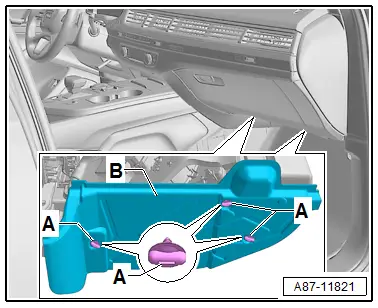
- Loosen the catches -A- and remove the shift cover -B-.
- Remove dust and pollen filter -E- from shaft -E- of the air intake housing -arrow-.
Installing
Install in reverse order of removal. Note the following:
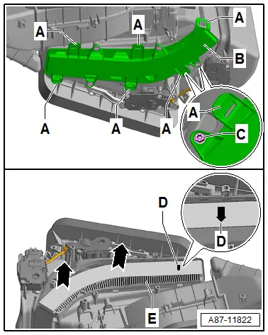
- Clean the air intake housing via the shaft for the dust and pollen filter (for example with a vacuum cleaner after removing the dust and pollen filter -E-).
- Insert the dust and pollen filter -E- on the proper side ("arrow"-D- points to the fresh air blower).
 Note
Note
- There are different versions of the dust and pollen filter as replacement part without and with filter insert with activated charcoal. Pay attention to the correct version. Refer to the Parts Catalog.
- If the catches -A- do not hold correctly, the shift cover -B- can also be secured with bolts -C- (for example 3.5 or 3.9 x 16 mm bolts, tightening specification 1 Nm). Refer to the Parts Catalog.
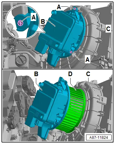
Fresh Air Blower -V2- with Fresh Air Blower Control Module -J126-, Removing and Installing
 Note
Note
- The Fresh Air Blower -V2- (and the Fresh Air Blower Control Module -J126-) -C- are one component. Do not take them apart. Refer to the Parts Catalog.
- The Fresh Air Blower -V2- (with the Fresh Air Blower Control Module -J126-) -C- as a replacement part is available in different versions. Ensure the correct allocation. Refer to the Parts Catalog.
- In the case of a switched on ignition and an activated Fresh Air Blower Control Module -J126-, the Fresh Air Blower -V2- connects the "plus" of contact "3" of connector -A- to the Fresh Air Blower -V2-. The speed of the Fresh Air Blower -V2- is regulated by the Fresh Air Blower Control Module -J126- via the ground connection of connector -A- contact "1". Refer to Vehicle Diagnostic Tester in the "Guided Fault Finding" function and → Wiring diagrams, Troubleshooting & Component locations.
- The Fresh Air Blower -V2- is activated (via the Fresh Air Blower Control Module -J126-) by the Fresh Air Blower Control Module -E87-, via a local data bus to contact "4" in connector -A-. Refer to Vehicle Diagnostic Tester in the "Guided Fault Finding" function and → Wiring diagrams, Troubleshooting & Component locations.
- In vehicles with a sliding sunroof with Solar Cells -C20- (optional equipment), the Fresh Air Blower -V2- is activated via the Fresh Air Blower Control Module -J126- when the ignition is off and sufficient voltage is present at contact "2" in connector -A-. The voltage at contact "2" in connector -C- depends on the sunlight on the Solar Cells -C20-.
Removing
- Move the right front seat (front passenger seat) as far back as possible.
- Turn off the ignition.
- Remove the glove compartment. Refer to → Body Interior; Rep. Gr.68; Storage Compartments and Covers; Glove Compartment, Removing and Installing.
- Remove the right (front passenger) footwell vent. Refer to → Chapter "Front Passenger Side Footwell Vent, Removing and Installing".

- Release the connector -A- and remove from the Fresh Air Blower -V2- (with the Fresh Air Blower Control Module -J126-) -C-.
- Remove the insulation -B-.
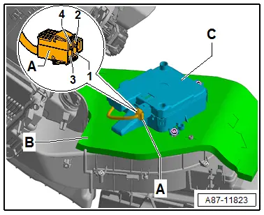
- Remove the bolts -A-.
 WARNING
The heat sink on Fresh Air Blower Control Module -J126- may be hot.
 Caution
Do not touch the fan wheel from the Fresh Air Blower -V2--D- and do not lay the fresh air blower on the fan wheel.
- Force against the fan wheel -D- or shifting the balancing weights fastened to fan wheel may cause imbalance and then problems during operation.
- Handle the fresh air blower -B- and fan wheel -D- very carefully.
 Note
Note
- When removing the Fresh Air Blower -V2--B- from the air intake housing -C- do not crush the fan wheel -D-. The fresh air blower -D- and the Fresh Air Blower -V2--B- can be damaged by even a brief application of force.
- Do not place the Fresh Air Blower -V2--B- on the fan wheel -D-.
- Remove the Fresh Air Blower -V2- (with the Fresh Air Blower Control Module -J126-) -B- carefully from air intake housing -C-.
Installing
Install in reverse order of removal. Note the following:
- Check air intake housing -C- via the shaft for the Fresh Air Blower -V2--B- for contamination and clean if necessary.
- When installing, make sure the Fresh Air Blower -V2--B- fits correctly in air intake housing -C-.
- Retrieve the Front A/C Display Control Head -E87- DTC memory and if necessary delete the displayed error. Refer to Vehicle Diagnostic Tester in the "Guided Fault Finding" function.
- To check the functionality, perform the output diagnostic test mode of the A/C system. Refer to Vehicle Diagnostic Tester in the "Guided Fault Finding" function.

