Audi Q7: Heater Core, Removing and Installing
Heater Core, Preparing for Removal
- Turn on the ignition.
- Adjust the airflow direction of the air on the Front A/C Display Control Head -E87- to "DEF" (to the windshield).
- Set the temperature preset on the Front A/C Display Control Head -E87- for the left and right side to "cold".
- Move the driver and passenger seats as far back as possible.
- Turn off the ignition.
- Remove the driver side instrument panel cover. Refer to → Body Interior; Rep. Gr.68; Storage Compartments and Covers; Driver Side Instrument Panel Cover, Removing and Installing.
- Remove the left footwell vent (driver side). Refer to → Chapter "Driver Side Footwell Vent, Removing and Installing".
- Remove the Rear Temperature Control Door Motor -V137-. Refer to → Chapter "Rear Temperature Control Door Motor -V137-, Removing and Installing".
- Remove the glove compartment. Refer to → Body Interior; Rep. Gr.68; Storage Compartments and Covers; Glove Compartment, Removing and Installing.
- If equipped, remove the air duct for the glove compartment cooling. Refer to → Chapter "Air Guide for Glove Compartment Cooling, Removing and Installing".
- Remove the Fresh Air Blower -V2- (with Fresh Air Blower Control Module -J126-). Refer to → Chapter "Fresh Air Blower -V2- with Fresh Air Blower Control Module -J126-, Removing and Installing".
Vehicles with a "Low" or "Mid" A/C system.
- Removing the Right Temperature Control Door Motor -V159-. Refer to → Chapter "Right Temperature Control Door Motor -V159-, Removing and Installing".
for vehicles with a "Mix" or "High" A/C system
- Remove the bracket for the right adjustment motors. Refer to → Chapter "Bracket for Right Adjustment Motors, Removing and Installing (on a Mix or High A/C System)".
- Remove the Rear Air Distribution Door Motor -V427- / Rear Air Quantity Motor -V443-. Refer to → Chapter "Rear Air Distribution Door Motor -V427- and Rear Air Quantity Motor -V443-, Removing and Installing".
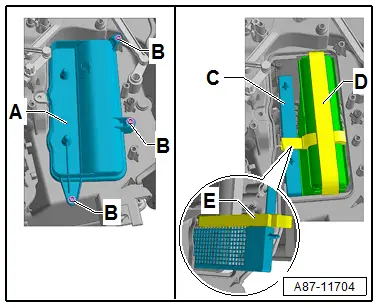
- Remove the bolts -B- and the cover -A- for the right heat exchanger.
- Remove the zone partition grille -C-.
Continued for All Engines
Refer to → Chapter "Heater Core, Removing and Installing"
Heater Core, Removing and Installing
Special tools and workshop equipment required
- Hose Clamps - Up To 25mm -3094- or Hose Clamps - Up To 40mm -3093-
- Commercial compressed-air gun with rubber end piece
- Cooling System Tester -VAG1274B- (and corresponding adapters)
Removing
- Perform the preparation work for removing the heater core. Refer to → Chapter "Heater Core, Preparing for Removal".
- Remove the plenum chamber cover. Refer to → Body Exterior; Rep. Gr.50; Bulkhead; Plenum Chamber Cover, Removing and Installing.
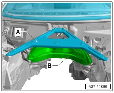
- Remove the tower brace -A-. Refer to → Suspension, Wheels, Steering; Rep. Gr.40; Suspension Strut and Upper Control Arm; Tower Brace, Removing and Installing.
 Note
Note
Disregard item -B-.
 WARNING
There is a risk of scalding from hot steam and coolant.
- The cooling system is under pressure when the engine is warm.
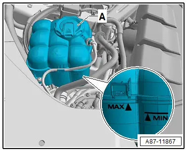
- To reduce the pressure, cover the coolant reservoir cap with cloths and then open it carefully.
- Carefully open the coolant expansion tank cap -A- (do not completely remove).
 Note
Note
There are different versions of the coolant expansion tank and in different allocations in the engine compartment. Refer to → Rep. Gr.19; Coolant System/Coolant; Coolant, Draining and Filling.
 Note
Note
- The heat exchanger is installed in the heater and A/C unit so that a specific flow direction of the coolant is necessary for clean bleeding of the heater core. Therefore, the coolant hoses must be connected on the correct side. Refer to → Chapter "Incorporating the Heating and A/C System in the Coolant Circuit".
- Bleed the coolant circuit. Refer to → Chapter "Coolant Circuit, Bleeding" and → Rep. Gr.19; Coolant System/Coolant; Coolant, Draining and Filling.
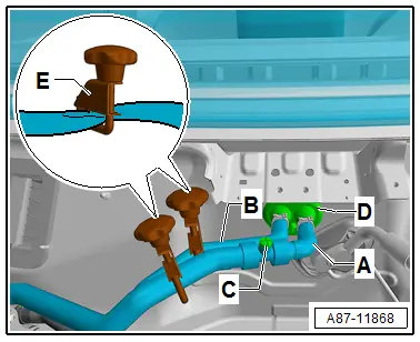
- Label the arrangement of the coolant hoses at the connections to the heater core -A- (supply from the Coolant Recirculation Pump -V50-) and -B- (return to the engine).
- Clamp the coolant hoses -A and B- with hose clamps -E-.
- Cover the area beneath connections for coolant hoses -A and B-, for example with absorbent paper.
- Place a small container under the connections for coolant hoses -A and B- (to the heater core).
 Note
Note
To prevent coolant from entering the plenum chamber when removing coolant hoses -A and B-.
- Remove the coolant hoses -A and B- from the connections to the heater and A/C unit heater core.

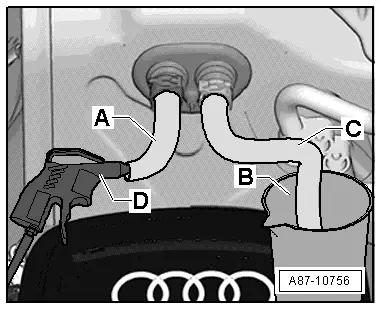
- Insert one section each of hose -A and B- on to both connections to heater core.
- Place a container -B- under the other end of the hose -C- .
- Using a compressed air gun -D-, carefully blow coolant out of the heater core against the normal flow direction of the coolant) via shaft -A- into container -B-.
- Cover the floor covering and the center tunnel under the left and right heater core -A- with a fluid-impermeable foil and absorbent paper.
- Remove the bolt from the screw-type clamp -B- and remove the screw-type clamp.
 Note
Note
- This illustration shows the layout on a vehicle with a "Mix" or "High" A/C system, on a vehicle with a "Low" or "Mid" A/C system the accessibility is easier (the Left Footwell Door Motor -V108--G- and the Left Footwell Temperature Control Door Motor -V411--H- are not installed).
- The bolts in the screw-type clamps -B and C- can be removed with a longer T15 Torx wrench -F-. Depending on the version of the heater and A/C unit for certain market specific vehicles instead of the Torx bolt, 3 mm hex socket bolt can be installed.
- If the screw-type clamps -B- and / or -C- are located unfavorably that the bolts are not accessible, these can be carefully turned if necessary (with slight force and a screwdriver).
- To improve the accessibility it can be helpful on a vehicle with a "Mix" or "High" A/C system to remove the Left Footwell Door Motor -V108--G- and Left Footwell Temperature Control Door Motor -V411--H-. Refer to → Chapter "Left Footwell Door Motor -V108-, Removing and Installing".
- If it is necessity due to the position of the screw-type clamps -B- and/or -C-, remove the bracket -J-. Refer to → Chapter "Rear Temperature Door Motor -V137- Bracket, Removing and Installing".
- Remove the bolt from the screw-type clamp -C- and remove the screw-type clamp.
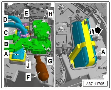
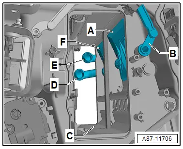
- Check the adjustment of the temperature control door for the right side -A- in the heater and A/C unit via the adjustment of the lever -B-, the lever -B- must be in the illustrated position.
 Caution
Risk of damaging the temperature control doors -A- in the heater and A/C unit when removing the heat exchanger.
Check via the lever -B- that the temperature control door -A- is in the "cold" position.
 Note
Note
The left temperature control door -F- is already positioned in the correct position before switching off the ignition. Refer to → Chapter "Heater Core, Preparing for Removal".
- Push the heat exchanger in the direction of the "right footwell" so that both coolant pipes -D and E- can be loosened from the heat exchanger connections.
- Remove the heat exchanger -A- in the direction of the -arrow- from the heater and A/C unit in the right footwell (front passenger side).

- Remove both O-ring seals from the coolant pipes -D and E- (or from the heat exchanger connections).

Installing
Install in reverse order of removal. Note the following:
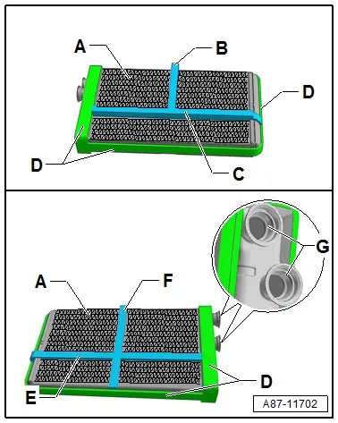
- Check the foam seals -B through E- on the heat exchanger -A- for damage and the correct bonding, only install a heat exchanger without damage and with securely bonded seals.
 Note
Note
- Via the foam seal -B and F- a separation takes place between the right and the left side on the heat exchanger -A-.
- Disconnect the foam seals -C and E- and the front and rear air duct through the heat exchanger.
- The foam seals -D- seal the heat exchanger ti the housing and outward.
- If the foam seals (-B to F-) are damaged are not bonded correctly, it can become loose when pushing in the heat exchanger the zone partition grille or the Auxiliary Heater Control Module -J604- (with the Auxiliary Heater Heating Element -Z35-) and when operating the A/C system can depending on the adjustment on the Front A/C Display Control Head -E87- lead to problems in the separation and regulation of the vent temperature sensor on the left and right side as well as between the rear and front. Noises can also result.
- If the foam seals (-B or F-) are not secure, secure or replace them. Refer to the Parts Catalog.
- If the foam seals (-B to F-) are damaged replace them. Refer to the Parts Catalog.
- Depending on the version of the heater and A/C unit the different foam seals are bonded to the heat exchanger. As a replacement part the heat exchanger comes with the seals for all versions of the heater and A/C unit installed. Later different heat exchangers will be available as a replacement part (with or without the foam seals -B, C, E, and F-) pay attention to the correct version and allocation to the heater and A/C unit. Refer to the Parts Catalog.
- Check the heater and A/C unit for contamination via the installation slot in the heat exchanger -C-.
- Remove any dirt or coolant which has leaked out from the heater and A/C unit (for example, after removing a leaking heater core).
- Check the installation slot for the upper and lower heat exchanger on both sides of the heater and A/C unit on the edges or protruding material.
- Remove any material left on the tool separation points during production of the heater and A/C unit and round any edges.
 Note
Note
During production of the heater and A/C unit, edges can be created at the tool separation points or material that protrudes beyond the heater and A/C unit can remain. On these positions the seals applied to the heat exchanger can be damaged when installing.
- Check the position of the temperature control door -A- for the right side and -F- for the left side in the heater and A/C unit, set the temperature control door to the illustrated position "cold".
 Caution
Risk of damaging the temperature control doors -A and F- in the heater and A/C unit when installing the heat exchanger.
The temperature control doors -A and F- must be in the illustrated position "cold".

- Check both connections -G- of the heat exchanger -A- for damage and contamination, then lightly moisten with coolant or coat with silicone grease.
 Note
Note
The silicone grease part number is G 000 405 A2. Refer to the Parts Catalog.

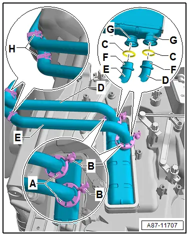
- Check the connection area -F- of both coolant pipes -D and E- to the heater core for damage or contamination.
- On both coolant pipes -D and E- respectively place a screw-type clamp -A- with a cylinder bolt -B- (M 4 x 16) mm on the correct side.
 Note
Note
From the manufacturer M 4 x 10 cylinder bolts are installed in both screw-type clamps, only with these bolts can the screw-type clamp be placed on the heat exchanger connections. When using the M 4 x 16 mm cylinder bolts the screw-type clamp can also be mounted with the cylinder bolt -B- pre-installed on the heat exchanger connection.
- Lightly moisten new seals -C- (contained in the heat core delivery) with coolant (or grease lightly with silicone grease).
- Install new seals -C- on both coolant pipes -D and E-.

 Caution
Risk of damaging the foam seals on the heat exchanger
So that the heat exchanger cannot be pushed too far into the heater and A/C unit. Before pushing the heat exchanger in the heater and A/C unit install the bracket for the Rear Temperature Control Door Motor -V137-. Refer to → Chapter "Rear Temperature Door Motor -V137- Bracket, Removing and Installing".
Risk of damaging the connections for the coolant pipes on the heat exchanger when inserting the heater and A/C unit.
- Have a second technician guide the heat exchanger when inserting, so that the connections -G- do not contact the heater and A/C unit housing and is not damaged.
- Push the heat exchanger slowly and carefully in the heater and A/C unit.
- As the second technician when installing the heat exchanger that the coolant pipes -D and E- (with the seals -C-) are guided in the heat exchanger connections.
- Have a second technician help push the heat exchanger -A- in the installation slot of the heater and A/C unit or to help when installing the heat exchanger as described above.

 Note
Note
- When inserting the heater core, ensure that both connections -G- and both coolant pipes -D and E- are not damaged.
- Do not bend the coolant pipes -D and E- when pushing them into the connections on the heater core.
- Make sure seals -C- on the coolant pipes -D and E- and in connections of heater core -G- fit securely.
 Caution
Seals that are incorrectly installed or jammed -C- will leak.
The seals -C- must be installed completely into both the coolant pipe connections -D and E- (in the flange connections of the heat exchanger -G-).
- Insert the coolant pipes -D and E- one after the other in the connections for the heat exchanger -G- and install the screw-type clamp -B- as shown on the connection point to the heat exchanger.

 Note
Note
- The screw-type clamps -B- engage when pressed together.
- The upper illustration shows the layout on a vehicle with a "Low" or "Mid" A/C system on a vehicle with a "Mix" or "High" A/C system (next illustration) the accessibility is more difficult (the Left Footwell Door Motor -V108--G- and the Left Footwell Temperature Control Door Motor -V411--H- or the corresponding bracket hinders the accessibility).
- This illustration shows the layout on a vehicle with a "Mix" or "High" A/C system.
- The bolts in the screw-type clamps -B and C- can be installed with a longer T15 Torx wrench -F-.
- If the screw-type clamps -B- and / or -C- are located unfavorably, these can be carefully turned before tighten (using slight force or a screwdriver).

- Secure the screw-type clamps -A- by tightening the bolt -B- (bolt tightening specification 2 Nm).
- Check the screw-type clamps -A- for proper seating on the connections of the heater core and the coolant pipes.
- Check the installation position of the screw-type clamps -A- and screws -A-. They must not be in contact with the heater and A/C unit or other components.
- Check the bracket for the coolant pipes -H- for correct seating.
Continuation for vehicles with an auxiliary heater
- Install the cover for the right heat exchanger and Auxiliary Heater Control Module - J604- (with Auxiliary Heater Heating Element - Z35-) in the heater and A/C unit. Refer to → Chapter "Auxiliary Heater Control Module -J604- (with Auxiliary Heater Heating Element -Z35-) Checking, Removing and Installing".
Continuation for vehicles without an auxiliary heater
- Check the foam seal -E- on the zone partition grille -C- for damage and proper adhesion.

 Note
Note
- If the foam seals -E- are damaged or not bonded correctly, they can become loose when pushing in the zone partition grille and when operating the A/C system can depending on the A/C system on the Front A/C Display Control Head -E87- lead to problems in the separation and regulation of the exterior temperature between the rear and front. Noises can also result.
- If the foam seals -E- is not secure, secure or replace it. Refer to the Parts Catalog.
- If the foam seals -E- is damaged, replace it. Refer to the Parts Catalog.
- Install the zone partition grille -C- and cover for the right heat exchanger -A- on the heater and A/C unit (bolt -B- tightening specification 1 Nm).
- Make sure the grommet -D- fits correctly in the back of the plenum chamber.
- Connect coolant hose -A- to the heater core coolant pipe (pay attention to the marking) and secure it with a clamp.
A - Supply to engine (or from the Coolant Recirculation Pump -V50-)
B - Return to the engine
- Install the coolant hose to heater core -B- on the coolant pipe so that air can still escape when ventilating the coolant circuit (do not push all the way on).
- Remove the hose clamp -E- from the coolant hose -A-.
- Fill the coolant expansion tank with coolant. Refer to → Rep. Gr.19; Coolant System/Coolant; Coolant, Draining and Filling.
- Screw the hand pump of the Cooling System Tester -VAG1274B- onto the filler neck of the coolant expansion tank.
- Carefully force the coolant out of the coolant overflow reservoir into the heater core using, for example, the hand pump from the Cooling System Tester -VAG1274B-.
- As soon as the coolant escapes from the connection point between coolant hose -B- and the coolant pipe of the heater core, push coolant hose -B- completely onto the coolant pipe.
- Secure coolant hose -B- with a clamp.
- Remove the hose clamp -E- from the coolant hose -B-.
- Open bleeder screw -C- and further ventilate the coolant circuit via bleeder screw -G-.
- Add more coolant to the coolant expansion tank, if necessary. Refer to → Rep. Gr.19; Coolant System/Coolant; Coolant, Draining and Filling.
 Note
Note
This procedure completely bleeds the cooling system. If, for some other reason, there is still some air in the cooling system, install all removed components and bleed the system once again. Refer to → Rep. Gr.19; Coolant System/Coolant; Coolant, Draining and Filling.
Check the connections at the heater core for leaks as follows:
- Carefully increase the pressure in the coolant circuit by using, for example, the hand pump of the Cooling System Tester -VAG1274B-.
- Check the coolant circuit for leaks. Pay particular attention to the connection between coolant hoses -D and E- and heat exchanger.

 Note
Note
- When bleeding the coolant circuit, take special care to ensure complete bleeding of the heater core. If there are still air bubbles in the heater core, it may cause the customer to complain of insufficient heating output in winter or different air temperature from vents at same setting in regulated mode. Refer to → Chapter "A/C System Temperature Door Heat Output Activation, Checking".
- Depending on vehicle equipment and on engine, heat insulation has been applied to coolant hoses, these must not be damaged and must be re-applied after installing.
- Reinstall all removed parts in the reverse order. Refer to → Chapter "Heater Core, Preparing for Removal".
- Perform the basic setting and the output diagnostic test mode (for functionality check) of the A/C system. Refer to Vehicle Diagnostic Tester in the "Guided Fault Finding" function.
 Note
Note
- In this vehicle, the actuators are equipped with electronics. During the basic setting, a new control motor learns its position on the heater and A/C unit and can then be activated by the Front A/C Display Control Head -E87- (currently all actuators are identical). Refer to Vehicle Diagnostic Tester in the "Guided Fault Finding" function.
- During the basic setting, the actuators are assigned and adapted corresponding to the switching sequence of the wiring. If this sequence does not conform with the specification, the actuators will adapt incorrectly and the door control will be wrong. Refer to → Chapter "Main Wiring Diagram for A/C System Actuators".
- Check the DTC memory on the Front A/C Display Control Head -E87- and erase any displayed malfunctions. Refer to Vehicle Diagnostic Tester in the "Guided Fault Finding" function.
- Adjust and check the air flow direction on the air duct via the Front A/C Display Control Head -E87-, if the quantity of air actually changes at each setting.

