Audi Q7: Balance Shaft
Overview - Balance Shaft
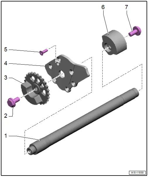
1 - Balance Shaft
- Removing and installing. Refer to → Chapter "Balance Shaft, Removing and Installing".
2 - Bolt
- 40 Nm +90º
- Replace after removing
- For loosening and tightening, use the Locating Pins -T40116- as a counterholder
3 - Balance Shaft Chain Sprocket
- With transmission side balance weight
4 - Gear Carrier
5 - Bolt
- 15 Nm
6 - Belt Pulley Side Balance Weight
- Can only be placed on the balance shaft in one position
7 - Bolt
- 40 Nm +90º
- Replace after removing
- For loosening and tightening, use the Locating Pins -T40116- as a counterholder
Balance Shaft, Removing and Installing
Special tools and workshop equipment required
- Locating Pins -T40116-
 Caution
This procedure contains mandatory replaceable parts. Refer to component overview prior to starting procedure.
Mandatory Replacement Parts
- Bolt - Balance shaft chain sprocket
- Bolt - Belt pulley side balance weight
Removing
- The transmission is removed. Refer to → 8-Speed Automatic Transmission 0D5; Rep. Gr.37; Transmission, Removing and Installing; Transmission, Removing.
- Remove the belt pulley side sealing flange. Refer to → Chapter "Sealing Flange, Removing and Installing, Belt Pulley Side".
- Remove the lower timing chain cover. Refer to → Chapter "Lower Timing Chain Cover, Removing and Installing".
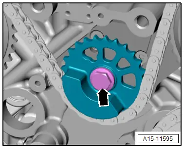
- Loosen the bolt -arrow- one turn to do so use the Locating Pins -T40116- as counterholder.
- Remove timing mechanism drive chain. Refer to → Chapter "Timing Mechanism Drive Chain, Removing and Installing".
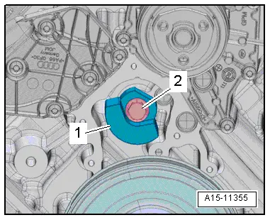
- Remove the bolt -2- on the engine belt pulley side, to do so counterhold the balance weight with the drift and balance shaft balance weight -1-.
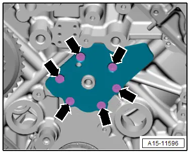
- Remove the bolts -arrows- and the balance shaft and bearing end bracket at the engine transmission side.
- Remove the balance shaft toward the rear out of the cylinder block.
Installing
Install in reverse order of removal and note the following:
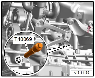
- Secure crankshaft in "TDC" position using Crankshaft Locking Pin -T40069-.
 Note
Note
The balance weights can only be positioned one way on balance shaft.
- Install timing mechanism drive chain. Refer to → Chapter "Timing Mechanism Drive Chain, Removing and Installing".
- Install the lower timing chain cover. Refer to → Chapter "Lower Timing Chain Cover, Removing and Installing".
- Install the belt pulley side sealing flange. Refer to → Chapter "Sealing Flange, Removing and Installing, Belt Pulley Side".
Tightening Specifications
- Refer to → Chapter "Overview - Balance Shaft"

