Audi Q7: Supercharger Belt Pulley, Removing and Installing
Special tools and workshop equipment required
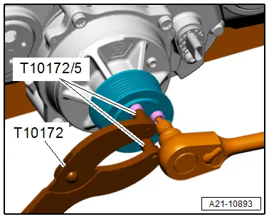
- Counterhold - Multiple Use -T10172A- with Counterhold - Kit - Adapter 5 -T10172/5-
 Caution
This procedure contains mandatory replaceable parts. Refer to component overview prior to starting procedure.
Mandatory Replacement Parts
- Bolts -Supercharger belt pulley
Removing
- Remove the engine cover. Refer to → Chapter "Engine Cover, Removing and Installing".
- Remove the supercharger ribbed belt. Refer to → Chapter "Ribbed Belt, Removing and Installing, Supercharger Ribbed Belt".
- Loosen the two belt pulley bolts a turn, while doing so counter hold on the other two bolts with the Counterhold - Kit - Multiple Use -T10172A- and Counterhold - Kit - Adapter 5 -T10172/5-.
- Place the counterholder on the loosened bolts and remove the two other bolts.
- Remove the remaining bolts and the belt pulley.
Installing
 Note
Note
Replace supercharger belt pulley bolts after removal.
Install in reverse order of removal and note the following:
- Install the supercharger ribbed belt. Refer to → Chapter "Ribbed Belt, Removing and Installing, Supercharger Ribbed Belt".
- Install the engine cover. Refer to → Chapter "Engine Cover, Removing and Installing".
Tightening Specifications
- Refer to → Chapter "Overview - Solenoid Coupling"
Operating Head, Removing and Installing
Special tools and workshop equipment required
- Used Oil Collection and Extraction Unit -SMN372500-
- Assembly Sleeve -T40318-, not illustrated
- Sealant. Refer to the Parts Catalog.
- Oil for the supercharger drive. Refer to the Parts Catalog.
- Expanding pliers (commercially available)
Removing
- Supercharger secured to engine/transmission holder for repair work. Refer to → Chapter "Supercharger, Securing to Engine/Transmission Holder for Repair Work".
- Remove the solenoid coupling. Refer to → Chapter "Solenoid Coupling, Removing and Installing".
- Hold the supercharger perpendicular on the engine/transmission holder.
- The drive head faces up.
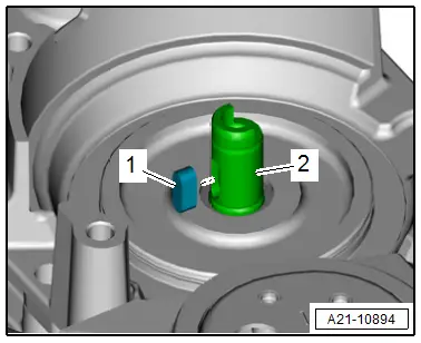
- Remove the woodruff key -1- from drive axle -2-.
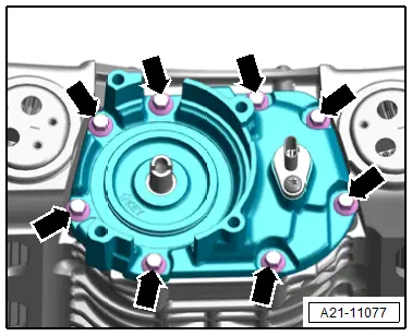
- Remove the bolts -arrows-.

 Caution
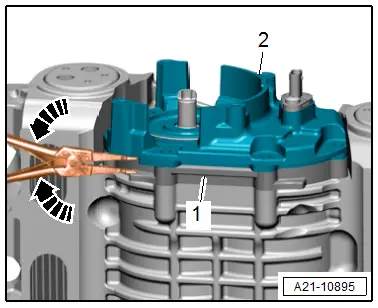
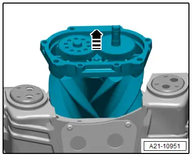
To prevent the rotor unit bearing cap -1- from coming and loose and having to be sealed again, do not use a hammer to remove the drive head -2- but rather use expanding pliers in direction of -arrows-, as illustrated.
- Carefully remove the operating head with expanding pliers from the bearing cap.
- Extract all the oil for the supercharger drive from the bearing cap as well as from the oil pockets -arrows- between the ribs using the Used Oil Collection and Extraction Unit -SMN372500-.
Installing
 Note
Note
- Replace the operating head gaskets after disassembly.
- Insert the self-locking bolts or bolts with sealant. Refer to the Parts Catalog.
- Clean any oil or grease off the sealing surfaces.
- Always clean the threaded holes with a thread tap before assembling.
- Fill the oil for the supercharger drive in the bearing cap.
 Note
Note
The container holds the exact amount. It is not necessary to check the oil level later.
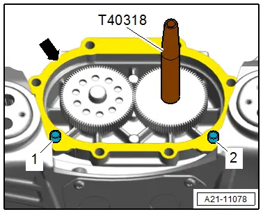
- Apply sealant thinly on the sealing surface -arrow- for the operating head on the rotor unit and place the Assembly Sleeve -T40318- on the drive axle as shown.
- Place the operating head with a new seal on the rotor unit, at the same time pay attention to the alignment sleeves -1 and 2-.
- Tighten the bolts -arrows-.
- Insert the woodruff key -1- in the drive axle -2-.
- Install the solenoid coupling. Refer to → Chapter "Solenoid Coupling, Removing and Installing".
Installation is performed in reverse order of removal, while noting the following:
- Check the supercharger for leaks. Refer to → Chapter "Supercharger, Checking for Leaks".

Tightening Specifications
- Refer to → Chapter "Overview - Rotor Unit"
Rotor Unit, Removing and Installing
Special tools and workshop equipment required
- Internal Puller -VAS501001-, not illustrated
- Thrust Piece -T40303-
 Caution
This procedure contains mandatory replaceable parts. Refer to component overview prior to starting procedure.
Mandatory Replacement Parts
- Needle Bearings - Rotor unit
Removing
- Supercharger secured to engine/transmission holder for repair work. Refer to → Chapter "Supercharger, Securing to Engine/Transmission Holder for Repair Work".
- Remove the solenoid coupling. Refer to → Chapter "Solenoid Coupling, Removing and Installing".
- Remove the operating head. Refer to → Chapter "Operating Head, Removing and Installing".
- Hold the supercharger perpendicular on the engine/transmission holder.
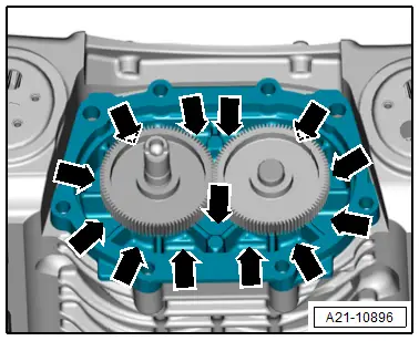
- The rotor unit spur gears point upward.
- Carefully remove the rotor unit upward in direction of -arrow- while doing so pay attention that the compressor housing rotors inner surfaces are not damaged.
- Place the rotor unit carefully aside and protect from dust.
- To prevent dirt and small parts from entering into the compressor housing, seal the air duct with clean cloths.
 Caution
There is a risk of damaging the compressor housing surfaces.
If required for the following steps protect the surfaces on the compressor housing with cloths.
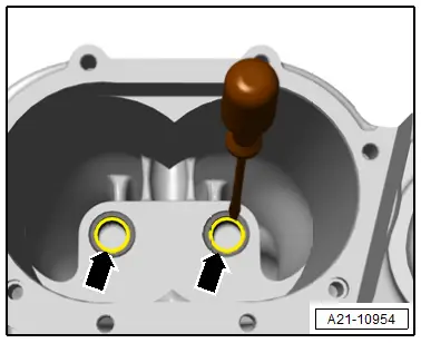
- Bend the seals -arrows- for the rotors needle bearing on both mounts toward the inside with a screwdriver.
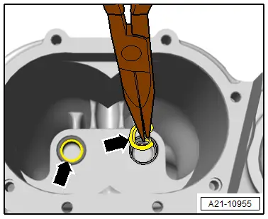
- Remove the seals -arrows- for the rotors needle bearing on both mounts with needle nose pliers.
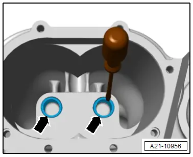
- Break off the needle bearing cages -arrows- on both mounts with a screwdriver.
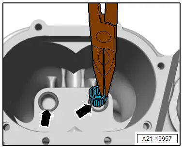
- Remove the needle bearing cages -arrows- from both mounts with needle nose pliers.
- Completely remove the loose mount rolls with a magnet.
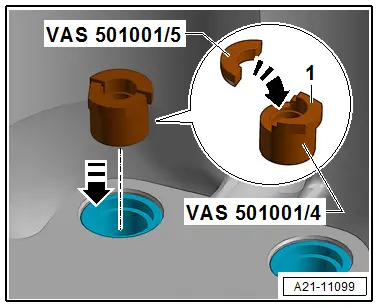
- Insert the Threaded Bushing - VAS501001/4- in the needle bearing sleeve, make sure that the collar -1- points upward.
- Place the Thrust Plate -VAS501001/5- on the Threaded Bushing - VAS501001/4- the tool labeling points upward.
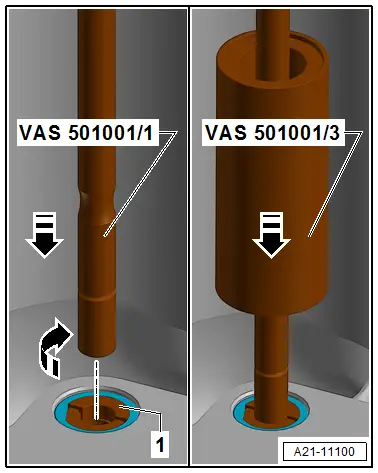
- Install the Spindle - VAS501001/1- all the way hand-tight in the Threaded Bushing -VAS501001/4--1-.
- Position the Press Sleeve -VAS501001/3- the end with the flat front side faces downward.
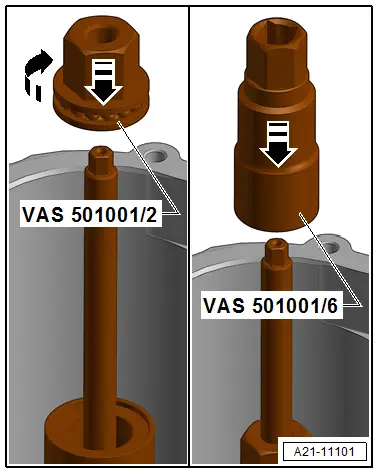
- Install the Thrust Nut -VAS501001/2- on the spindle.
- Place the Internal Puller - Socket -VAS501001/6- on the thrust nut.
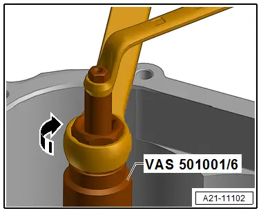
- Remove the needle bearing sleeve by turning the Internal Puller - Socket -VAS501001/6-. At the same time, use a suitable tool to counterhold at the Internal Puller - Spindle -VAS501001/1-.
- Remove the sleeve from the second needle bearing in the same way.
Installing
- Always clean the bearing seats and bolting surfaces for the rotor unit.
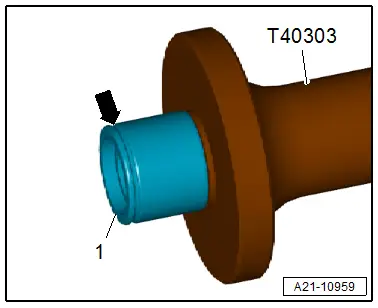
- Place the new needle bearing on the Thrust Piece - T40303-.
- The groove -arrow- points to the compressor housing.
- The seal in the needle bearing points to the tool.
 Caution
There is a risk of thinning the grease in the needle bearing from applying too much engine oil.
Only apply engine oil very thinly.
- Coat the outer edge (sleeve) of the needle bearing with engine oil.
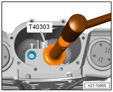
- Place the needle bearing with the Thrust Piece -T40303- straight in the compressor housing hole and drive in all the way with a large plastic mallet.
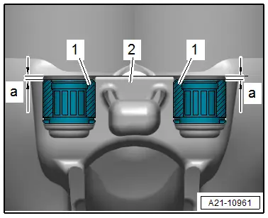
- After driving in the needle bearing -1- check its seating in the compressor housing -2-.
- Dimension -a- = 1.5 mm
- If required drive in the needle bearing further.
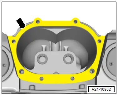
- Apply a thin coat of sealant -arrow- on the rotor unit sealing surface for the compressor housing.
- Carefully insert the rotor unit in the compressor housing.
- Pay attention that the supercharger housing rotors inner surfaces are not damaged and that the rotor axles are guided into the needle bearing.
- Install the operating head. Refer to → Chapter "Operating Head, Removing and Installing".
- Install the solenoid coupling. Refer to → Chapter "Solenoid Coupling, Removing and Installing".
- Check the supercharger for leaks. Refer to → Chapter "Supercharger, Checking for Leaks".
Input Shaft Seal, Replacing
Special tools and workshop equipment required
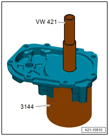
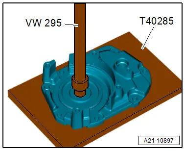
- Bearing/Bushing Installer - Multiple Use -VW295-
- Bearing Installer - Wheel Bearing -3144-
- Plate -T40285-
 Caution
This procedure contains mandatory replaceable parts. Refer to component overview prior to starting procedure.
Mandatory Replacement Parts
- Seal - Input shaft
Procedure
- Remove the operating head. Refer to → Chapter "Operating Head, Removing and Installing".
- Place the operating head with the front side upward on the Plate -T40285- as shown in the illustration.
- Drive out the seal from the operating head using the Bearing/Bushing Installer - Multiple Use -VW295- .
- Place the operating head with the front side downward on the workbench.
- Drive in the gasket with the Bearing Installer - Wheel Bearing -3144-.
- Installation position: the open side of the gasket points to the tool.
- Install the operating head. Refer to → Chapter "Operating Head, Removing and Installing".