Audi Q7: Pistons and Connecting Rod
Overview - Pistons and Connecting Rod
 Note
Note
- Lubricate all bearing and contact surfaces when assembling.
- Oil spray jet for piston cooling. Refer to → Fig. "Oil Spray Jet for Piston Cooling".
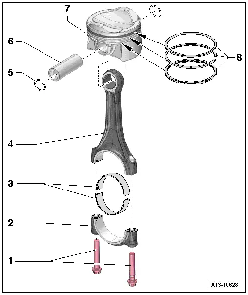
1 - Bolts
- 50 Nm +90º
- Replace after removing
- Use old bolts for the radial clearance measurement
- Lubricate the threads and contact surface.
2 - Connecting Rod Bearing Cap
- Mark for reinstallation
- Use color to identify the cylinder and connecting rod to which it belongs. Refer to → Fig. "Connecting Rod, Marking"
- Installation position of the connecting rod pairs. Refer to → Fig. "Connecting Rod Installation Position"
3 - Bearing Shells
- Make sure the retaining tabs are secure.
- Replace any worn bearing shells
- Oversized bearings are available for reworked crankshaft connecting rod journals. Refer to the Parts Catalog.
- The connecting rod bearing tabs are above each other
4 - Connecting Rod
- Always replace as a set
- Use color to identify the cylinder and the connecting rod bearing cap to which it belongs. Refer to → Fig. "Connecting Rod, Marking"
- Installation position of the connecting rod pairs. Refer to → Fig. "Connecting Rod Installation Position"
- Axial clearance for each new connecting rod pair: 0.20 to 0.45 mm
- Radial play, measuring. Refer to → Chapter "Connecting Rods, Checking Radial Clearance".
5 - Circlip
- Replace after removing
6 - Piston Pin
- Removing and installing. Refer to → Chapter "Pistons, Removing and Installing".
7 - Piston
- Label the installation position and cylinder allocation. Refer to → Fig. "Piston Installation Position".
- Removing and installing. Refer to → Chapter "Pistons, Removing and Installing".
- Replace the piston if there are cracks on the piston crown or piston shaft
- Check piston and cylinder bore. Refer to → Chapter "Piston and Cylinder Bore, Checking".
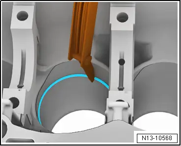
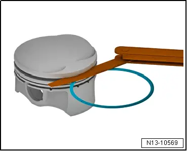
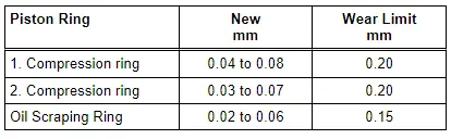
8 - Piston Rings
- Measuring the gap. Refer to → Fig. "Piston Ring Gap, Measuring".
- Measuring side clearance. Refer to → Fig. "Piston Ring Height Clearance, Measuring".
- Use piston ring pliers (commercially available) for removing and installing
- Installation position: "TOP" lettering or side with lettering faces the piston crown.
- Offset gaps by 120º
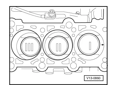
Piston Installation Position
 Caution
Risk of destroying the coating on the piston crown.
Mark the allocation to the cylinder on the piston crown with paint to reinstall used pistons. Do not mark the piston crown with a punch, notch or something similar.
- The arrows on the piston crowns point to the belt pulley side.
Connecting Rod, Marking
 Note
Note
- Only replace connecting rod as a set.
- Do not interchange connecting rod bearings.
- Mark the connecting rod and connector rod bearing cap to each other and to the cylinder -arrow- with paint for reinstallation.
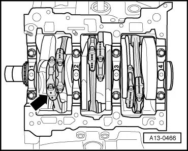
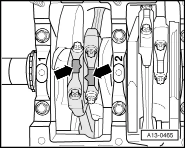
Connecting Rod Installation Position
- The molded tabs -arrows- on the beveled surfaces of the connecting rod pairs "1 and 2", "3 and 4" and "5 and 6" must face each other.
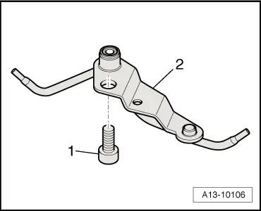
Oil Spray Jet for Piston Cooling
1 - Insert the bolt with locking compound and tighten to 9 Nm. Refer to the Parts Catalog for the locking compound.
2 - Oil spray jet with spray nozzle valve (opening pressure 2 to 2.4 bar (29 to 34.8 psi) )
 Caution
Risk of damaging the oil spray jets.
- Do not bend the oil spray jets.
- Bent oil spray jets must be replaced.
Pistons, Removing and Installing
 Caution
This procedure contains mandatory replaceable parts. Refer to component overview prior to starting procedure.
Mandatory Replacement Parts
- Circlip - Piston pin
- Bolts - Connecting rod bearing cap
Special tools and workshop equipment required
- Pilot Drift -VW222A-
- Commercially Available Piston Ring Compressor
Removing
- Engine is secured to the Engine and Gearbox Bracket -VAS6095A-. Refer to → Chapter "Engine, Securing to Engine and Transmission Holder".
- Remove the cylinder head. Refer to → Chapter "Cylinder Head, Removing and Installing".
- Remove the oil pan upper section. Refer to → Chapter "Oil Pan Upper Section, Removing and Installing".
- Mark the installation position and the connecting rod bearing cap allocation to the cylinder and connecting rod for installing again later. Refer to → Fig. "Connecting Rod, Marking".
- Remove the connecting rod bearing cap.
- Remove the piston with the connecting rod upward.
 Note
Note
Warm the piston to approximately 60 ºC (140 ºF) if it is difficult to move the piston pin.
- Remove the circlip from the piston pin eye.
- Remove the piston pin using the Pilot Drift -VW222A-.
Installing
Install in reverse order of removal and note the following:
 Note
Note
Replace the bolts that were tightened with an additional turn after removing them.
- Coat the contact surfaces on the bearing shells with oil.
- Install the piston with the piston ring compressor.
Installation position:
- Piston. Refer to → Fig. "Piston Installation Position".
- Connecting rod. Refer to → Fig. "Connecting Rod Installation Position".
- Install the connecting rod bearing cap according to the marking.
- Install the oil pan upper section. Refer to → Chapter "Oil Pan Upper Section, Removing and Installing".
- Install the cylinder head. Refer to → Chapter "Cylinder Head, Removing and Installing".
Tightening Specifications
- Refer to → Chapter "Overview - Pistons and Connecting Rod"
Piston and Cylinder Bore, Checking
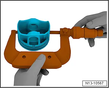
Pistons, Checking
- Measure approximately 15 mm from the lower edge at a 90º angle to the piston pin axis using a 75 to 100 mm external micrometer.
- Maximum deviation from the specified size: 0.03 mm.
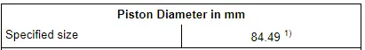
1) Measurements with coating (thickness approximately 0.02 mm). The coating wears off.
Cylinder Bore, Measuring
- Using the Cylinder Dial Bore Gauge -VAS6078-, measure in a diagonal sequence at three positions transversely -A- and longitudinally -B-.
- Maximum variance from the specified size: 0.08 mm.
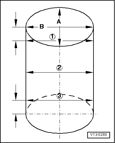
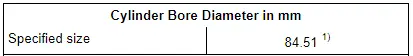
1) measure 50 mm inside the cylinder bore.
Piston Ring Gap, Measuring
- At a right angle to the cylinder wall, push the piston ring from above down into the lower cylinder opening until it is approximately 15 mm from the edge of the cylinder.
- Use a piston without a piston ring for pushing it in.
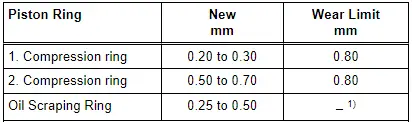
1) Not determined yet.
Piston Ring Height Clearance, Measuring
- Clean the piston ring groove before checking.
Connecting Rods, Checking Radial Clearance
Special tools and workshop equipment required
- Plastigage
 Caution
This procedure contains mandatory replaceable parts. Refer to component overview prior to starting procedure.
Mandatory Replacement Parts
- Bolts - Connecting Rod Bearing Cap
Procedure
 Note
Note
Use old bolts to measure radial clearance measurement.
- Remove the connecting rod bearing cap.
- Clean the bearing cap and pin.
- Place the Plastigage over the entire width of the bearing journal or into the bearing shells.
- Position the connecting rod bearing cap and fasten with the old bolts -1- . Do not turn the crankshaft at the same time.
- Remove the connecting rod bearing cap again.
- Compare the width of the Plastigage with the measuring scale.
Radial clearance:
- New: 0.010 to 0.052 mm.
- Wear limit: 0.120 mm.
- Replace the bolts for the final assembly.
Special Tools
Special tools and workshop equipment required
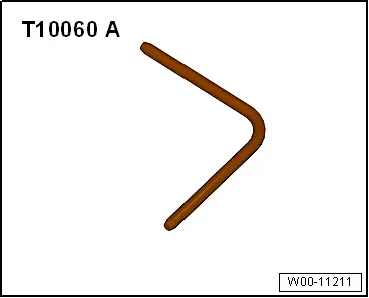
- Locking Pin -T10060A-
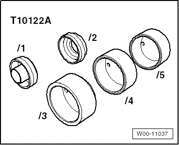
- Crankshaft Seal Installer Kit -T10122A-
- Crank Shaft Seal Installer - Guide Piece -T10122/6-
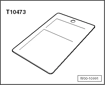
- Gauge - Sender Wheel -T10473-
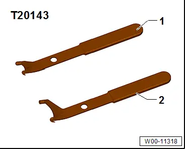
- Puller - Crankshaft/Power Steering Seal -T20143/2-
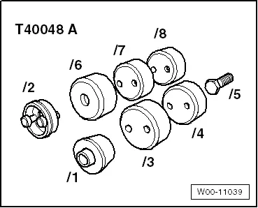
- Assembly Tool -T40048A-
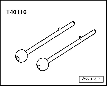
- Locating Pins -T40116-
- Dial Gauge - 0-10mm -VAS6079-
- Pilot Drift -VW222A-
- Dial Gauge Holder -VW387-
- Counterhold - Flywheel -10-201-
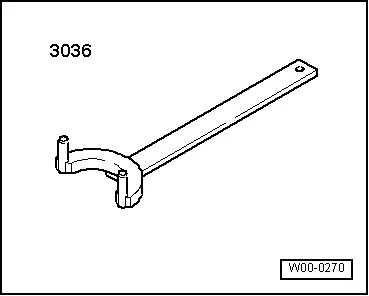
- Wrench - Pin Type -3036-
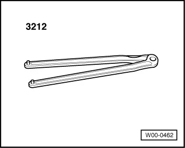
- Wrench - Pin Type -3212-
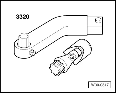
- Wrench - Door Adjusting - Box Wrench -3320/2- from Wrench - Door Adjusting -3320-