Audi Q7: Battery Test with Vehicle Diagnostic Tester
The Battery -A- can also be checked using the Vehicle Diagnostic Tester when it is installed and without being connected to a battery charger.
Special tools and workshop equipment required
- Vehicle Diagnostic Tester
Test Prerequisites
- No battery charger connected
- Battery -A- is connected.
- Battery temperature at least +10 ºC (50 ºF).
Procedure
Vehicle Diagnostic Tester is attached.
- Select the Diagnostic mode and start the diagnostics.
- Select the tab Test Plan.
- Select Select Individual Tests and choose the following sequence.
- Body
- Electrical Equipment
- 27 - Starter, voltage supply
- Electrical Components
- A - Battery, Checking
The Vehicle Diagnostic Tester continues with the battery test from here on.
Battery Tester -VAS6161-
General Description:
 WARNING
Risk of injury. Follow all warning messages and safety precautions. Refer to → Chapter "Warnings and Safety Precautions".
It is not necessary to disconnect or remove the Battery -A- when using the Battery Tester -VAS6161-.
The Battery Tester -VAS6161- does not load the Battery -A-. It is working according to the principle of dynamic conductivity.
The Battery Tester -VAS6161- stores all battery types.
The data can be stored on an SD memory card.
The Battery Tester -VAS6161- can be updated via an interface or a SD card, so that all battery data from Volkswagen is always current.
The integrated infrared sensor (measuring the battery temperature) increases the quality of the measurements.
As an option, there is a scanner available, which can be used to read the bar code on the Battery -A-.
 Note
Note
Observe the Battery Tester -VAS6161- Operating Instructions.
- Battery Tester -VAS6161- device description. Refer to → Chapter "Battery Tester -VAS6161- Device Description".
- Battery test. Refer to → Chapter "Battery Test, Performing using Battery Tester -VAS6161-".
- Maintenance test, performing. Refer to → Chapter "Maintenance Test, Performing".
- Service test, performing. Refer to → Chapter "Service Test, Performing".
- Warranty test, performing. Refer to → Chapter "Warranty Test, Performing".
- Printed test results explanations. Refer to → Chapter "Explanation of Test Results".
- Test result evaluation. Refer to → Chapter "Test Result Evaluation".
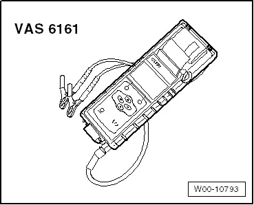
Battery Tester -VAS6161- Device Description
Battery Tester -VAS6161-
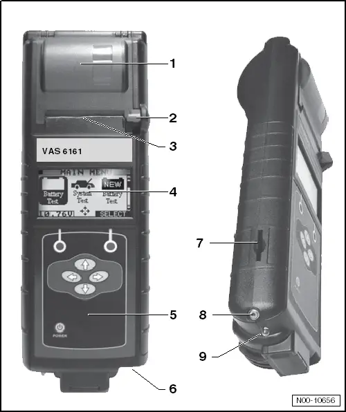
1 - Internal printer
2 - Operating lever for the paper tray
3 - Paper slot
4 - Main menu display
5 - Display with on/off-button
6 - Connection for the battery tester cable
7 - Slot for the SD memory card
8 - Infrared temperature sensor
9 - PC file transmitter
Battery Test, Performing using Battery Tester -VAS6161-
Special tools and workshop equipment required
- Battery Tester -VAS6161-
 WARNING
Risk of injury. Follow all warning messages and safety precautions. Refer to → Chapter "Warnings and Safety Precautions".
Procedure
 WARNING
Do not check or charge a Battery -A- when the visual indicator has "no color or is bright yellow". Jump starting must not be used!
There is a risk of explosion during testing, charging or jump starting.
These Batteries -A- must be replaced.
 Note
Note
The Battery -A- temperature must be at least 10 ºC (50 ºF).
- Turn off the ignition and all electrical consumers and remove the ignition key.
- Check the visual indicator on Batteries -A- with visual indicator. Refer to → Chapter "Battery, Checking, Vehicles with Battery Monitoring Control Module J367 or Energy Management Control Module J644 and Data Bus On Board Diagnostic Interface J533".
- Switch on the Battery Tester -VAS6161-. Refer to → Chapter "Battery Tester -VAS6161- Device Description".
- Connect the red terminal (+) to the positive terminal of the Battery -A-.
- Connect the black terminal (-) to the negative terminal for the Battery -A-.
 Note
NoteMake sure the test terminals make good contact!
- Select one of the following:
- Maintenance test (only on new vehicles before becoming inventory). Refer to → Chapter "Maintenance Test, Performing".
- Service test. Refer to → Chapter "Service Test, Performing".
- Warranty test. Refer to → Chapter "Warranty Test, Performing".
 Note
Note
- The test is over after approximately 10 seconds.
- The results of the test are output through the printer.
- The Battery Tester -VAS6161- does not have to cool down before taking the next measurement.
- Switch off the Battery Tester -VAS6161-. Refer to → Chapter "Battery Tester -VAS6161- Device Description".
- Remove the test terminals.
Maintenance Test, Performing
 WARNING
Do not check or charge a Battery -A- when the visual indicator has "no color or is bright yellow". Jump starting must not be used!
There is a risk of explosion during testing, charging or jump starting.
These Batteries -A- must be replaced.
Procedure
- Select "Maintenance Test".
- Connect the scanner.
 Note
Note
If there is no scanner, manually enter the VIN on the printed test results.
- Scan the VIN.
- Select "at the battery pole" or "at the battery jump start terminal".
- Section vehicle model.
- Scan the barcode or manually select the "type and manufacturer" in the menu.
- Determine the temperature above the Battery -A-. Hold the infrared sensor approximately 5 cm above the battery pole until the temperature is stable.
- Start the test.
- Print out the test notes.
Service Test, Performing
 WARNING
Do not check or charge a Battery -A- when the visual indicator has "no color or is bright yellow". Jump starting must not be used!
There is a risk of explosion during testing, charging or jump starting.
These Batteries -A- must be replaced.
Procedure
- Select "Service Test".
- Select "at the battery pole" or "at the battery jump start terminal".
- Section vehicle model.
- Determine the temperature above the Battery -A-. Hold the infrared sensor approximately 5 cm above the battery pole until the temperature is stable.
- Select battery type (Normal, AGM, 2*6 V or Gel).
- Select Norm (CCA, JIS, DIN, SAE, IEC or EN).
- Start the test.
- Print out the test notes.
Warranty Test, Performing
 WARNING
Do not check or charge a Battery -A- when the visual indicator has "no color or is bright yellow". Jump starting must not be used!
There is a risk of explosion during testing, charging or jump starting.
These Batteries -A- must be replaced.
Procedure
- Select "Warranty Test".
- Select "inside the vehicle" or "outside of the vehicle".
- Select "at the battery pole" or "at the battery jump start terminal".
- Section vehicle model.
- Determine the temperature above the Battery -A-. Hold the infrared sensor approximately 5 cm above the battery pole until the temperature is stable.
- Select battery type (Normal, AGM, 2*6 V or Gel).
- Select battery capacity.
- Start the test.
- Print out the test notes.
Explanation of Test Results
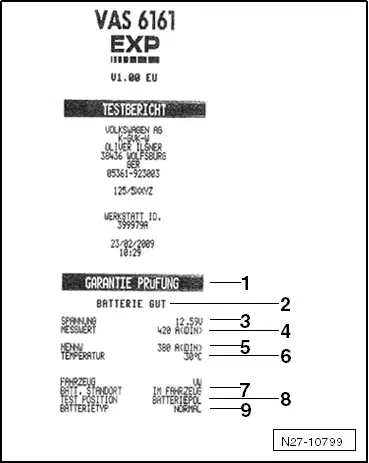
1 - Type of test
2 - Test result
3 - Measured voltage
4 - Battery -A- measured cold start value
5 - Battery -A- cold start value set on the Battery Tester -VAS6161-
6 - Temperature measured above the Battery -A-
7 - Battery -A- component location
8 - Battery terminal clamp position set on the Battery Tester -VAS6161-
9 - Selected battery type
 Note
Note
The printed test results are required for warranty claims.
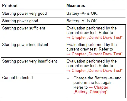
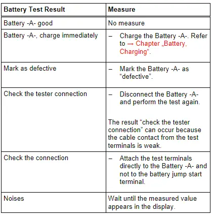
Test Result Evaluation
Evaluating the Battery Test Results for the Warranty and Service Tests
Evaluating the Battery Test Results for the Maintenance test
Battery Tester with Printer -VAS5097A-
 WARNING
Risk of injury. Follow all warning messages and safety precautions. Refer to → Chapter "Warnings and Safety Precautions".
It is not necessary to disconnect or remove the Battery -A- when using the Battery Tester with Printer -VAS5097A-.
The following Batteries -A- can be tested using the Battery Tester with Printer -VAS5097A-:
- 80 to 499 A cold crank amps according to German Industry Standardization DIN (Deutsche Industrie Norm). Refer to → Note.
- 95 to 574 A cold cranking output according to IEC (International Engineering Consortium)
- 136 to 855 A cold cranking output according to EN/ SAE (Europäische Norm/ Standard of Automotive Engineers)
1) Batteries -A- with cold crank amps greater than 499 A according to DIN can be tested with the setting for 499 A according to DIN.
The Batteries -A- are tested by being loaded with current that corresponds to the starter current of a vehicle. Under this load, the Battery -A- is evaluated and the measured results are output through the printer.
 Note
Note
Read the Battery Tester with Printer -VAS5097A- Operating Instructions and Battery Tester with Printer -VAS5097A- Quick Reference Guide label on the Battery Tester with Printer -VAS5097A- and the cold crank amps table. Refer to → Chapter "Cold Crank Amps Table".
- Battery Tester with Printer -VAS5097A- device description. Refer to → Chapter "Battery Tester with Printer -VAS5097A- Device Description".
- Battery load test. Refer to → Chapter "Battery Load Test".
- Cold crank amps table. Refer to → Chapter "Cold Crank Amps Table".
- Battery load test results. Refer to → Chapter "Battery Load Test Results".
- Printed test results explanations. Refer to → Chapter "Printed Test Results Explanations".
- Test result evaluation. Refer to → Chapter "Test Result Evaluation".
Battery Tester with Printer -VAS5097A- Device Description
Battery Tester with Printer -VAS5097A-
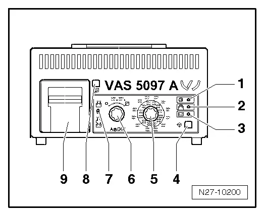
1 - LED green, "Device in use"
2 - LED red, "Device connected with terminals reversed"
3 - LED red "Battery cannot be tested", the Battery -A- must be replaced.
4 - Start button
5 - Cold cranking output selector switch
6 - ON/OFF function switch
7 - Sliding switch (battery hook-up to the Battery -A-/at jump start point)
8 - Paper-feed -button
9 - Printer
Battery Load Test
 WARNING
Risk of injury. Follow all warning messages and safety precautions. Refer to → Chapter "Warnings and Safety Precautions".
Special tools and workshop equipment required
- Battery Tester with Printer -VAS5097A-
Always note the TPL 2012182.
Procedure
 WARNING
Do not check or charge a Battery -A- when the visual indicator has "no color or is bright yellow". Jump starting must not be used!
There is a risk of explosion during testing, charging or jump starting.
These Batteries -A- must be replaced.
 Note
Note
The Battery -A- temperature must be at least 10 ºC (50 ºF).
 Caution
- Turn off the ignition and all electrical equipment.
- Remove the key.
- Check the visual indicator on Batteries -A- with visual indicator. Refer to → Chapter "Battery, Checking, Vehicles with Battery Monitoring Control Module J367 or Energy Management Control Module J644 and Data Bus On Board Diagnostic Interface J533".
- Switch on the Battery Tester with Printer -VAS5097A-. Refer to → Chapter "Battery Tester with Printer -VAS5097A- Device Description".
- Determine the cold crank amps according to specifications on the Battery -A- in ampere (A) according to DIN and determine the Battery Tester With Printer -VAS5097A- adjustment range using the table. Refer to → Chapter "Cold Crank Amps Table".
 Note
Note
If the Battery -A- does not state this value in DIN but rather in IEC or EN/SAE, then convert the value using the table (refer to → Chapter "Cold Crank Amps Table") or the table on the Battery Tester with Printer -VAS5097A-.
- Set the cold crank amps with the cold crank amps selector switch. Refer to → Chapter "Battery Tester with Printer -VAS5097A- Device Description".
- Set the measuring range (80 to 379 A or 380 to 499 A) using the ON/OFF switch. Refer to → Chapter "Battery Tester with Printer -VAS5097A- Device Description".
 Note
Note
Batteries -A- with cold crank amps greater than 499 A according to DIN can be tested with the setting for 499 A according to DIN.
- Connect the red terminal (+) to the positive terminal of the Battery -A-.
- Connect the black terminal (-) to the negative terminal for the Battery -A-.
 Note
Note- Make sure the test terminals make good contact!
- Note TPL 2012182 for the Battery Tester with Printer -VAS5097A-.
- Using the sliding switch, select the test clamp connection point. Refer to → Chapter "Battery Tester with Printer -VAS5097A- Device Description".
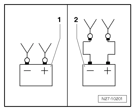
1 - Direct connection to the Battery -A-
2 - Connection on the battery jump start terminal
- Check if the cold crank amps indicated on the Battery -A- matches the selected value on the Battery Tester with Printer -VAS5097A-.
- Press theStart-button. Refer to → Chapter "Battery Tester with Printer -VAS5097A- Device Description".
The green LED lights up. Refer to → Chapter "Battery Tester with Printer -VAS5097A- Device Description". The test program runs automatically. The test results are output through the printer. Refer to → Chapter "Battery Load Test Results". If the Battery Tester with Printer -VAS5097A- does not start, (the LED does not come on and there is no print out), then charge the Battery -A-. Refer to → Chapter "Battery, Charging".
- Switch off the Battery Tester with Printer -VAS5097A-. Refer to → Chapter "Battery Tester with Printer -VAS5097A- Device Description".
- Remove the test terminals.
 Note
Note
- The test is over after approximately 20 seconds.
- The results of the test are output through the printer.
- Only perform the test once. Repeating the test will not produce accurate results.
- The Battery Tester with Printer -VAS5097A- needs 30 minutes to cool off before it is ready for the next measurement.
Cold Crank Amps Table
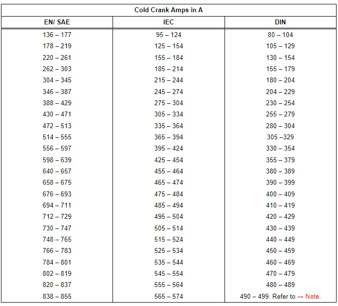
1) Batteries -A- with cold crank amps greater than 499 A according to DIN can be tested with the setting for 499 A according to DIN.
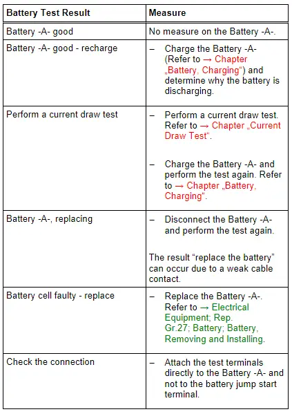
Battery Load Test Results
By placing the battery under a strong load during the Battery -A- load test, the battery voltage will be reduced.
- If the Battery -A- is good, the voltage drops only to the specified minimum voltage.
- If the Battery -A- is defective or weakly charged, the battery voltage will drop very quickly to below the specified minimum voltage.
- After testing, this low voltage level is maintained for a lengthy period and only increases again slowly.
- Only perform the test once. Repeating the test will not produce accurate results.
- In order to be able to test another/additional Battery -A-, the Battery Tester with Printer -VAS5097A- must cool down for approximately 30 minutes for the test result to be correct.
Printed Test Results Explanations
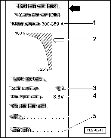
1 - Measuring range set on the Battery Tester with Printer -VAS5097A-
2 - Diagram, the -arrow- points to the Battery -A- status.
3 - Test result
4 - Battery -A- voltage during the battery load test.
5 - Vehicle data and date. For tester to fill out.
 Note
Note
- The printed test results are required for warranty claims.
- Only perform the test once. Repeating the test will not produce accurate results.
Test Result Evaluation