Audi Q7: Expansion Valve, Removing and Installing
Refrigerant Lines, Disconnecting from Front Expansion Valve and Reconnecting
 Caution
This procedure contains mandatory replaceable parts. Refer to component overview prior to starting procedure.
Mandatory Replacement Parts
- O-ring - Front Expansion Valve to Refrigerant Line - High Pressure Side
 Caution
Danger due to refrigerant coming out under pressure.
Danger of frost bite to skin and other parts of the body.
Only loosen the connection point bolts when the refrigerant circuit is empty.
Removing
- Turn off the ignition.
- Discharge the refrigerant circuit. Refer to → Refrigerant R134a Servicing; Rep. Gr.87; Refrigerant Circuit.
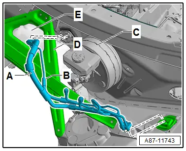
- Remove the tower brace -D-. Refer to → Suspension, Wheels, Steering; Rep. Gr.40; Suspension Strut and Upper Control Arm; Tower Brace, Removing and Installing.
- Loosen the lower plenum chamber bulkhead -E- from the vehicle and move to the side (do not remove). Refer to → Body Exterior; Rep. Gr.50; Bulkhead; Overview - Bulkhead.

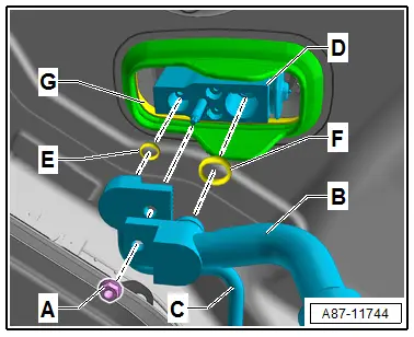
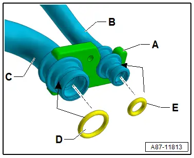
- Remove the nut -A-. Refer to → Chapter "Overview - Refrigerant Lines in Plenum Chamber and Front Expansion Valve" for the tightening specification.
- Remove both refrigerant lines -B and C- from the front expansion valve -D-. Refer to → Chapter "Refrigerant Lines, Disconnecting from Front Expansion Valve and Reconnecting".
 Note
Note
Immediately seal off any open line connections and connection points with clean plugs, for example, taken from the Engine Bung Set -VAS6122-.
Installing
Installation is done is reverse order, observe the following:
- Check the support ring -G- for proper installation position and check the grommet in the plenum chamber rear wall for damage and proper installation.
- Thoroughly clean all connections in expansion valve -D- and at refrigerant lines -B and C- and check for damage.
- Replace the O-ring seals -E and F-. Refer to the Parts Catalog for the correct version.
 Note
Note
Follow the instructions for installing the O-rings. Refer to → Chapter "Refrigerant Circuit Seals".
- Coat the O-ring seals lightly with refrigerant oil before installing. Refer to → Chapter "Refrigerant Circuit Seals".
- Make sure the O-ring seals fit properly inside the grooves in the connections of refrigerant lines -B and C-.
- Tighten the nut -A- for the refrigerant lines -B and C-.
- Nut -A- tightening specification: 9 Nm.
- Check the routing of the refrigerant lines after attachment. They must be inserted in the provided brackets in a tension-free manner and must not come in contact with other components.

- Install the lower plenum chamber bulkhead -E-. Refer to → Body Exterior; Rep. Gr.50; Bulkhead; Overview - Bulkhead.
- Install the tower brace -D-. Refer to → Suspension, Wheels, Steering; Rep. Gr.40; Suspension Strut and Upper Control Arm; Tower Brace, Removing and Installing.
- Evacuate and charge the refrigerant circuit. Refer to → Refrigerant R134a Servicing; Rep. Gr.87; Refrigerant Circuit.
- Install the remaining removed components.
- Retrieve the Front A/C Display Control Head -E87- DTC memory and if necessary delete the displayed error. Refer to Vehicle Diagnostic Tester in the "Guided Fault Finding" function.
- Operate the A/C system after charging the refrigerant circuit. Refer to → Chapter "A/C System, Starting after Charging Refrigerant Circuit".
 Note
Note
Note the information regarding operating the A/C system after filling. Refer to → Refrigerant R134a Servicing; Rep. Gr.87; A/C System, General Information.
Front Expansion Valve, Removing and Installing
 Caution
This procedure contains mandatory replaceable parts. Refer to component overview prior to starting procedure.
Mandatory Replacement Parts
- O-ring - Front Expansion Valve to Refrigerant Line - High Pressure Side
 Note
Note
After switching off the A/C compressor in this vehicle, it may take a relatively long time for the pressure on the high pressure side to decrease. This is because the expansion valve is cold and the pressure on the low pressure side increases quickly after shutting the compressor off, then the expansion valve closes and the refrigerant flows slowly to the low pressure side. If the A/C compressor is switched on, the pressure on the low pressure side goes down, the expansion valve open and the refrigerant can flow of the low pressure side.
Removing
- Turn off the ignition.
- Discharge the refrigerant circuit. Refer to → Refrigerant R134a Servicing; Rep. Gr.87; Refrigerant Circuit.
- Remove the tower brace -D-. Refer to → Suspension, Wheels, Steering; Rep. Gr.40; Suspension Strut and Upper Control Arm; Tower Brace, Removing and Installing.
- Loosen the lower plenum chamber bulkhead -E- from the vehicle and move to the side (do not remove). Refer to → Body Exterior; Rep. Gr.50; Bulkhead; Overview - Bulkhead.
- Disconnect the refrigerant lines -A and B- from the front expansion valve and put aside (do not remove). Refer to → Chapter "Refrigerant Lines, Disconnecting from Front Expansion Valve and Reconnecting".

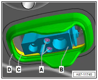
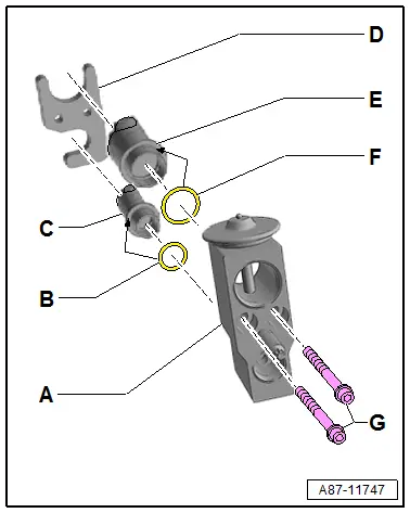
- Remove the bolts -A-.
- Disconnect the expansion valve -B- from the refrigerant lines leading to the evaporator.
 Note
Note
Immediately seal off any open line connections and connection points with clean plugs, for example, taken from the Engine Bung Set -VAS6122-.
Installing
Installation is done is reverse order, observe the following:
- Check the support ring -D- for proper installation position and check the grommet in the plenum chamber rear wall for damage and proper installation.
- Clean the connecting tubes -B and C- from the evaporator and check for damage.
- Check the baseplate -D- on the connecting tubes -B and C- is seated correctly on the connecting tubes to the evaporator.
- Replace the O-ring seals -E and F-. Refer to the Parts Catalog for the correct version.
 Note
Note
- Follow the instructions for installing the O-rings. Refer to → Chapter "Refrigerant Circuit Seals".
- The retaining plate -A- must be installed in the mounts from the connecting tubes -B and C-.
- The O-ring seals -D and E- are inserted in the groove from the connecting tubes -B and C- .
- Coat the O-ring seals lightly with refrigerant oil before installing. Refer to → Chapter "Refrigerant Circuit Seals".
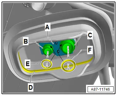
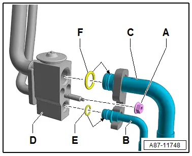
- Clean the connections on the expansion valve -A- (to the connecting tubes -C and E-) to the evaporator and check for damage.
 Note
Note
The expansion valve -A- is available in different versions (same housing but a different control characteristic). Refer to the Parts Catalog for the exact allocation.
- Replace the O-ring seals -B and F-. Refer to the Parts Catalog for the correct version.
- Make sure the retaining plate -D- fits correctly on the connection pipes -C and E- leading to the evaporator.
- Tighten the bolts -G-.
- Tightening specification: 9 Nm
- Connect the refrigerant line to the expansion valve. Refer to → Chapter "Refrigerant Lines, Disconnecting from Front Expansion Valve and Reconnecting".
- Evacuate and charge the refrigerant circuit. Refer to → Refrigerant R134a Servicing; Rep. Gr.87; Refrigerant Circuit.
- Install the remaining removed components.
- Retrieve the Front A/C Display Control Head -E87- DTC memory and if necessary delete the displayed error. Refer to Vehicle Diagnostic Tester in the "Guided Fault Finding" function.
- Operate the A/C system after charging the refrigerant circuit. Refer to → Chapter "A/C System, Starting after Charging Refrigerant Circuit".
 Note
Note
Note the information regarding operating the A/C system after filling. Refer to → Refrigerant R134a Servicing; Rep. Gr.87; A/C System, General Information.
Refrigerant Lines from Rear Expansion Valve, Disconnecting and Connecting
 Caution
This procedure contains mandatory replaceable parts. Refer to component overview prior to starting procedure.
Mandatory Replacement Parts
- O-ring - Rear Expansion Valve to Refrigerant Line - High Pressure Side
- O-ring - Rear Expansion Valve to Refrigerant Line - Low Pressure Side
 Caution
Danger due to refrigerant coming out under pressure.
Danger of frost bite to skin and other parts of the body.
Only loosen the connection point bolts when the refrigerant circuit is empty.
 Note
Note
- After the A/C compressor is switched off in this vehicle, it may take a relatively long time for the pressure on the high pressure side to decrease (the expansion valve(s) is/are cold, the pressure on the low pressure side increases quickly after deactivation, the expansion valve(s) closes/close and the refrigerant can only flow slowly to the low pressure side).
- There are different versions of the expansion valve (and thus different refrigerant lines to the expansion valve) depending on the production period. Therefore, ensure proper allocation. Refer to the Parts Catalog.
Remove the Refrigerant Lines
- Turn off the ignition.
- Discharge the refrigerant circuit. Refer to → Refrigerant R134a Servicing; Rep. Gr.87; Refrigerant Circuit.
- Remove the left underbody trim panel. Refer to → Body Exterior; Rep. Gr.66; Underbody Trim Panel; Underbody Trim Panels, Removing and Installing.
- Remove the heat shield for the transmission tunnel. Refer to → Body Exterior; Rep. Gr.66; Moldings, Trims, Extensions and Trim Panels; Floor Heat Shield, Removing and Installing.
- Loosen the heat shield mat on the left center tunnel in the area of the transmission from the vehicle.
- Loosen the bracket for the refrigerant lines from the underbody. Refer to → Chapter "Overview - Expansion Valve and Refrigerant Lines to Rear Heater and A/C Unit".
- Remove the nut -A-.
- Remove the refrigerant lines -B and C- from the expansion valve -D-.
 Note
Note
Immediately seal off any open line connections and connection points with clean plugs, for example, taken from the Engine Bung Set -VAS6122-.
Installing
Installation is done is reverse order, observe the following:
- Clean refrigerant line connections on expansion valve -D- and on refrigerant lines -B and C-, and check for damage.
- Replace the O-ring seals -E and F-. Refer to the Parts Catalog for the correct version.
 Note
Note
- Follow the instructions for installing the O-rings. Refer to → Chapter "Refrigerant Circuit Seals".
- Make sure the O-ring seals fit correctly inside the grooves of the connections.
- Coat the O-rings -E and F- with refrigerant oil before installing. Refer to → Chapter "Refrigerant Circuit Seals".
- Insert refrigerant lines -B and C- on expansion valve.
- Insert and tighten the nut -A-.
- Tightening specification of nut -A- (with a thread "M6") 9 Nm.
 Note
Note
- Install the refrigerant lines such that they are not strained.
- Following attachment, check routing of refrigerant lines -B and C- on the expansion valve. They must be inserted in brackets provided and not make contact with other components.
- Check the routing of the refrigerant lines after attachment. They must be inserted in the provided brackets in a tension-free manner and must not come in contact with other components.
- Evacuate and charge the refrigerant circuit. Refer to → Refrigerant R134a Servicing; Rep. Gr.87; Refrigerant Circuit.
- Install the remaining removed components.
- Retrieve the Front A/C Display Control Head -E87- DTC memory and if necessary delete the displayed error. Refer to Vehicle Diagnostic Tester in the "Guided Fault Finding" function.
- Operate the A/C system after charging the refrigerant circuit. Refer to → Chapter "A/C System, Starting after Charging Refrigerant Circuit".

 Note
Note
Note the information regarding operating the A/C system after filling. Refer to → Refrigerant R134a Servicing; Rep. Gr.87; A/C System, General Information.

