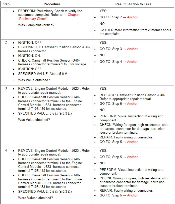
Audi Q7: Camshaft Position Sensor - G40-, Checking
General Description
Using the signal from the Camshaft Position Sensor -G40-, the precise position of the camshaft relative to the crankshaft is determined very quickly when the engine is started. Used in combination with the signal from the Engine Speed Sensor -G28-, the signal from the Camshaft Position Sensor -G40- allows the Engine Control Module -J623- to detect which cylinder is at TDC. The fuel can be injected into the corresponding cylinder and ignited.
Special tools and workshop equipment required
- Multimeter.
- Wiring Diagram.
- Scan Tool.
Test requirements
- Fuses OK.
- Battery voltage OK.
- Switch OFF all electrical and electronic accessories.
- Vehicles with automatic transmission, ensure the selector lever position is in "P".
- Vehicles with manual transmission, ensure the shifter lever position is in "N" with the parking brake applied.
- Coolant temperature: ≥ 80º C.
- Observe all safety precautions: → Chapter "Safety Precautions".
- View clean working conditions: → Chapter "Clean Working Conditions".
- For Hybrid vehicles, refer to: → Chapter "High Voltage System General Warnings".
Test Procedure

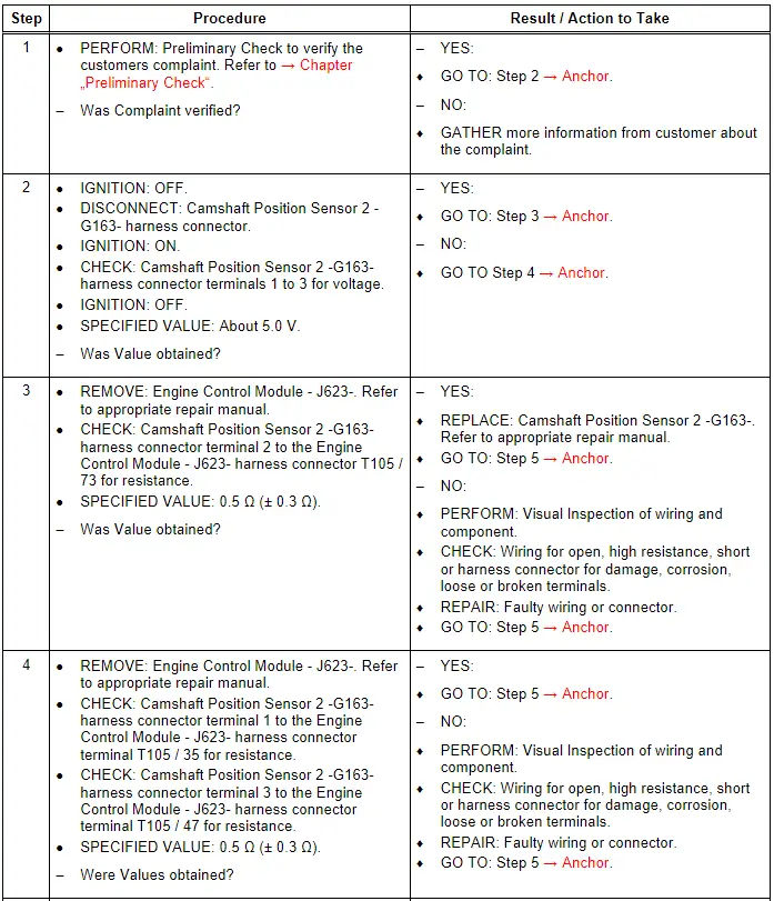
Camshaft Position Sensor 2 - G163-, Checking
General Description
Using the signal from the Camshaft Position Sensor 2 -G163-, the precise position of the camshaft relative to the crankshaft is determined very quickly when the engine is started. Used in combination with the signal from the Engine Speed Sensor -G28-, the signal from the Camshaft Position Sensor 2 -G163- detects which cylinder is at TDC. The fuel can be injected into the corresponding cylinder and ignited. In case of signal failure, the signal from the Engine Speed Sensor -G28- is used instead. Because the camshaft position and the cylinder position cannot be recognized as quickly, it may take longer to start the engine.
Special tools and workshop equipment required
- Multimeter.
- Wiring Diagram.
- Scan Tool.
Test requirements
- Fuses OK.
- Battery voltage OK.
- Switch OFF all electrical and electronic accessories.
- Vehicles with automatic transmission, ensure the selector lever position is in "P".
- Vehicles with manual transmission, ensure the shifter lever position is in "N" with the parking brake applied.
- Coolant temperature: ≥ 80º C.
- Observe all safety precautions: → Chapter "Safety Precautions".
- View clean working conditions: → Chapter "Clean Working Conditions".
- For Hybrid vehicles, refer to: → Chapter "High Voltage System General Warnings".
Test Procedure

Camshaft Position Sensor 3 - G300-, Checking
General Description
Camshaft position sensors are located at each camshaft for control and monitoring of the camshaft adjusters. For exact determination of the camshaft adjustment, the basic settings (retard position) of the four camshafts are learned by the control modules (adaptation). During adaptation, the Camshaft solenoid valves are de-energized. The camshafts are moved to retard position (basic setting) both by the setting of the solenoid valves and the direction of pull exerted by the chain. The position of the camshaft position sensor signals relative to the engine speed sensor reference mark (actual values), is stored as basic position and compared to the specified values.
This provides the basic values for camshaft timing control. A distinction is made between basic and fine adaptation. Basic adaptation is always implemented after the ECM is de-energized (no Terminal 30) or erasing of DTCs. After starting the engine, the camshafts briefly remains in the basic position until the exact position of the camshafts with respect to the crankshaft has been established. If the camshafts are already in basic position (valves de-energized) and the coolant temperature is greater than 185º F (85º C), and assuming basic adaptation has been implemented, fine adaptation is always performed briefly several times (for approximately one second) after starting the engine. Adaptation of the inlet camshafts takes place at idle or in the near idle range. Adaptation of the exhaust camshafts takes place in the engine speed range between 1,200 and 2,000 RPM and at low engine load. The camshaft timing control function is disabled if adaptation is not performed successfully.
Special tools and workshop equipment required
- Multimeter.
- Wiring Diagram.
- Scan Tool.
Test requirements
- Fuses OK.
- Battery voltage OK.
- Switch OFF all electrical and electronic accessories.
- Vehicles with automatic transmission, ensure the selector lever position is in "P".
- Vehicles with manual transmission, ensure the shifter lever position is in "N" with the parking brake applied.
- Coolant temperature: ≥ 80º C.
- Observe all safety precautions: → Chapter "Safety Precautions".
- View clean working conditions: → Chapter "Clean Working Conditions".
- For Hybrid vehicles, refer to: → Chapter "High Voltage System General Warnings".
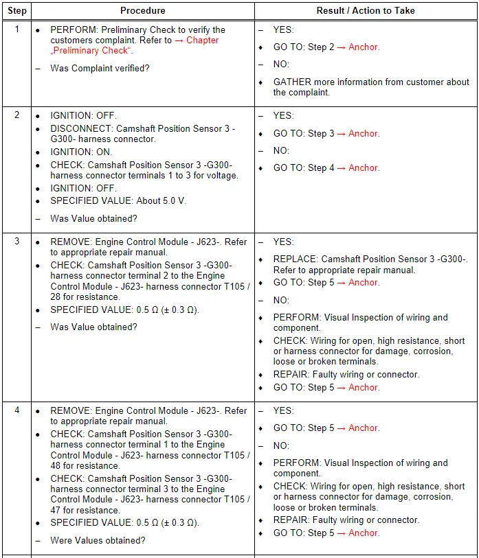
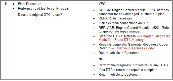
Test Procedure
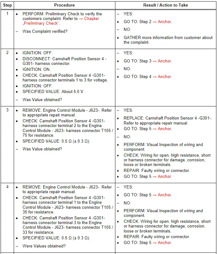
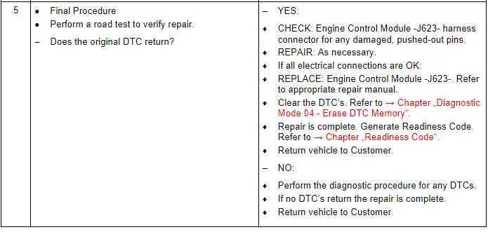
Camshaft Position Sensor 4 - G301-, Checking
General Description
Camshaft position sensors are located at each camshaft for control and monitoring of the camshaft adjusters. For exact determination of the camshaft adjustment, the basic settings (retard position) of the four camshafts are learned by the control modules (adaptation). During adaptation, the Camshaft solenoid valves are de-energized. The camshafts are moved to retard position (basic setting) both by the setting of the solenoid valves and the direction of pull exerted by the chain. The position of the camshaft position sensor signals relative to the engine speed sensor reference mark (actual values), is stored as basic position and compared to the specified values.
This provides the basic values for camshaft timing control. A distinction is made between basic and fine adaptation. Basic adaptation is always implemented after the ECM is de-energized (no Terminal 30) or erasing of DTCs. After starting the engine, the camshafts briefly remain in the basic position until the exact position of the camshafts with respect to the crankshaft has been established. If the camshafts are already in basic position (valves de-energized) and the coolant temperature is greater than 185º F (85º C), and assuming basic adaptation has been implemented, fine adaptation is always performed briefly several times (for approximately one second) after starting the engine. Adaptation of the inlet camshafts takes place at idle or in the near idle range. Adaptation of the exhaust camshafts takes place in the engine speed range between 1200 and 2000 RPM and at low engine load. The camshaft timing control function is disabled if adaptation is not performed successfully.
Special tools and workshop equipment required
- Multimeter.
- Wiring Diagram.
- Scan Tool.
Test requirements
- Fuses OK.
- Battery voltage OK.
- Switch OFF all electrical and electronic accessories.
- Vehicles with automatic transmission, ensure the selector lever position is in "P".
- Vehicles with manual transmission, ensure the shifter lever position is in "N" with the parking brake applied.
- Coolant temperature: ≥ 80º C.
- Observe all safety precautions: → Chapter "Safety Precautions".
- View clean working conditions: → Chapter "Clean Working Conditions".
- For Hybrid vehicles, refer to: → Chapter "High Voltage System General Warnings".
Test Procedure