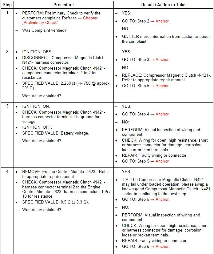
Audi Q7: Compressor Magnetic Clutch - N421-, Checking
General Description
The supercharger Compressor Magnetic Clutch -N421- is controlled by the engine control module (ECM) as required, i.e. the clutch is only engaged when high engine output is requested. The Compressor Magnetic Clutch -N421- is engaged and forms a frictional connection between the belt pulley and the supercharger's driveshaft, which is located in the hub. The Compressor Magnetic Clutch -N421- is disengaged and the supercharger is not driven when the engine output requirement is low.
Special tools and workshop equipment required
- Multimeter.
- Wiring Diagram.
- Scan Tool.
Test requirements
- Fuses OK.
- Battery voltage OK.
- Switch OFF all electrical and electronic accessories.
- Vehicles with automatic transmission, ensure the selector lever position is in "P".
- Vehicles with manual transmission, ensure the shifter lever position is in "N" with the parking brake applied.
- Coolant temperature: ≥ 80º C.
- Observe all safety precautions: → Chapter "Safety Precautions".
- View clean working conditions: → Chapter "Clean Working Conditions".
- For Hybrid vehicles, refer to: → Chapter "High Voltage System General Warnings".
Test Procedure

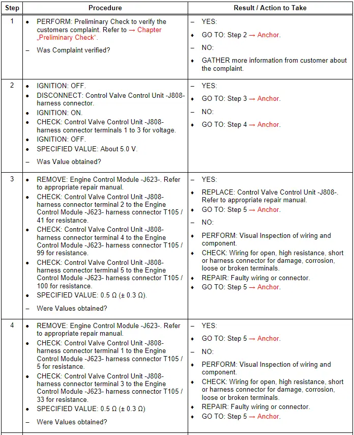
Control Valve Control Unit - J808-, Checking
General Description
The Engine Control Module -J623- computes the nominal charge pressure from the requested torque. If the actual charge pressure deviates from the nominal charge pressure, the wastegate is opened further by the Control Door Adjustment Motor -V380- (charge pressure decreases) or closed further (charge pressure increases). The rapid response of the Control Door Adjustment Motor -V380- ensures that the wastegate opens quickly in overrun mode, thereby reducing the pumping effort of the turbocharger. The wastegate is closed in the start position. The Control Door Adjustment Motor -V380- is activated by the PWM signal, and the Control Valve Position Sensor -G584- provides position feedback.
The Control Valve Control Unit -J808- contains the following components:
- Control Door Adjustment Motor -V380-
- Control Valve Position Sensor -G584-
The Control Valve Control Unit -J808- components cannot be serviced separately, and they must be serviced as a unit.
Special tools and workshop equipment required
- Multimeter.
- Wiring Diagram.
- Scan Tool.
Test requirements
- Fuses OK.
- Battery voltage OK.
- Switch OFF all electrical and electronic accessories.
- Vehicles with automatic transmission, ensure the selector lever position is in "P".
- Vehicles with manual transmission, ensure the shifter lever position is in "N" with the parking brake applied.
- Coolant temperature: ≥ 80º C.
- Observe all safety precautions: → Chapter "Safety Precautions".
- View clean working conditions: → Chapter "Clean Working Conditions".
- For Hybrid vehicles, refer to: → Chapter "High Voltage System General Warnings".
Test Procedure
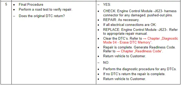
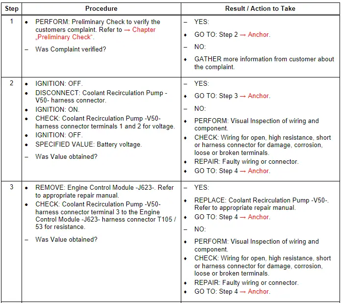
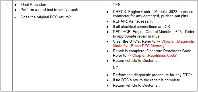
Coolant Recirculation Pump - V50-, Checking
General Description
The Coolant Recirculation Pump -V50- is cycled on and off by the Engine Control Module -J623-.
Special tools and workshop equipment required
- Multimeter.
- Wiring Diagram.
- Scan Tool.
Test requirements
- Fuses OK.
- Battery voltage OK.
- Switch OFF all electrical and electronic accessories.
- Vehicles with automatic transmission, ensure the selector lever position is in "P".
- Vehicles with manual transmission, ensure the shifter lever position is in "N" with the parking brake applied.
- Coolant temperature: ≥ 80º C.
- Observe all safety precautions: → Chapter "Safety Precautions".
- View clean working conditions: → Chapter "Clean Working Conditions".
- For Hybrid vehicles, refer to: → Chapter "High Voltage System General Warnings".
Test Procedure
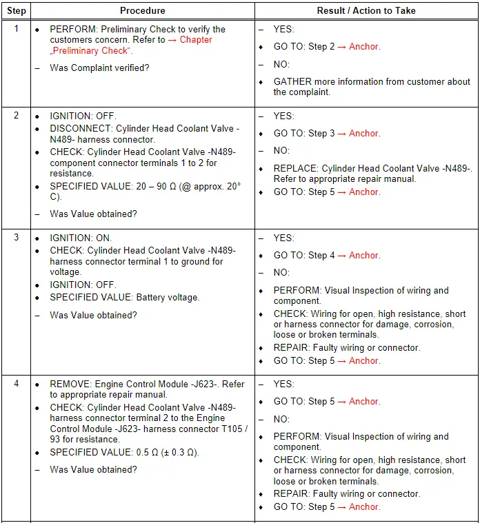
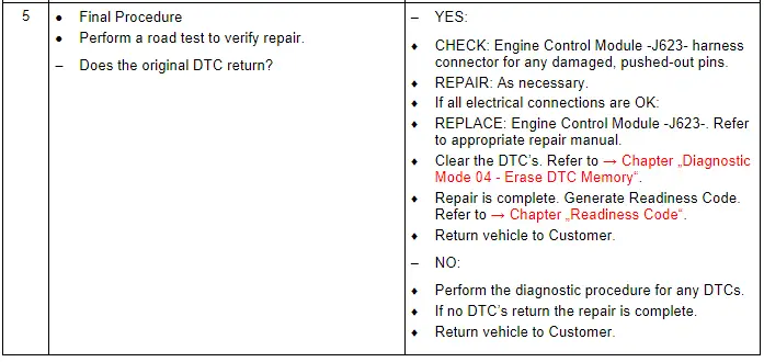
Cylinder Head Coolant Valve - N489-, Checking
General Description
Coolant flow is regulated by means of two mechanically coupled rotary slide valves. The angular position of the rotary slide valves is regulated according to various engine maps stored in the engine control unit. Various switching positions can be implemented by configuring the rotary slide valves accordingly. This allows rapid heating of the engine, which, in turn, results in lower friction and higher fuel economy.
Special tools and workshop equipment required
- Multimeter.
- Wiring Diagram.
- Scan Tool.
Test requirements
- Fuses OK.
- Battery voltage OK.
- Switch OFF all electrical and electronic accessories.
- Vehicles with automatic transmission, ensure the selector lever position is in "P".
- Vehicles with manual transmission, ensure the shifter lever position is in "N" with the parking brake applied.
- Coolant temperature: ≥ 80º C.
- Observe all safety precautions: → Chapter "Safety Precautions".
- View clean working conditions: → Chapter "Clean Working Conditions".
- For Hybrid vehicles, refer to: → Chapter "High Voltage System General Warnings".
Test Procedure