Audi Q7: CAN-Bus Terminal Resistance, Checking
General Description
The Engine Control Module -J623- communicates with other CAN-Bus capable control modules.
The control modules are connected by two data bus wires which are twisted together (CAN_High and CAN_Low), and exchange information (messages). Missing information on the CAN-bus is recognized as a malfunction by the Engine Control Module -J623- and the other control modules connected to the CAN-bus.
Trouble-free operation of the CAN-Bus requires that it have a terminal resistance. This central terminal resistance is located in the Engine Control Module -J623-.
Special tools and workshop equipment required
- Multimeter.
- Wiring Diagram.
Test requirements
- Fuses OK.
- Battery voltage OK.
- Switch OFF all electrical and electronic accessories.
- Vehicles with automatic transmission, ensure the selector lever position is in "P".
- Vehicles with manual transmission, ensure the shifter lever position is in "N" with the parking brake applied.
- Coolant temperature: ≥ 80º C.
- Observe all safety precautions: → Chapter "Safety Precautions".
- View clean working conditions: → Chapter "Clean Working Conditions".
- For Hybrid vehicles, refer to: → Chapter "High Voltage System General Warnings".
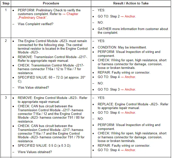
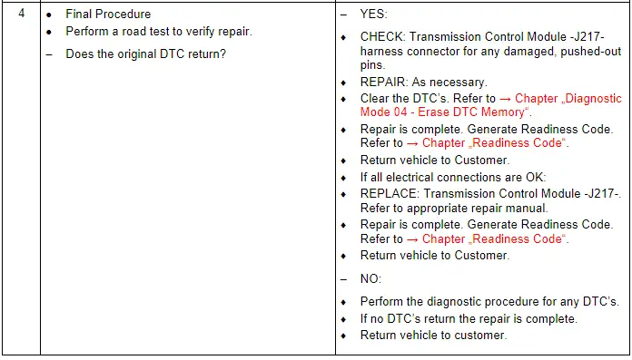
Test Procedure
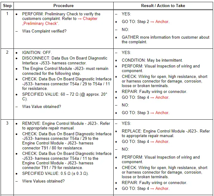
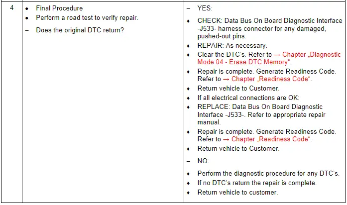
CAN-Bus Terminal Resistance, Powertrain, Checking
General Description
The Engine Control Module -J623- communicates with all databus capable control modules via a CAN databus.
These databus capable control modules are connected via two data bus wires which are twisted together (CAN_High and CAN_Low), and exchange information (messages). Missing information on the databus is recognized as a malfunction and stored.
Trouble-free operation of the CAN-bus requires that it have a terminal resistance. The central terminal resistor is located in the Engine Control Module -J623-.
Special tools and workshop equipment required
- Multimeter
- Wiring Diagram
Test requirements
- Fuses OK.
- Battery voltage OK.
- Switch OFF all electrical and electronic accessories.
- Vehicles with automatic transmission, ensure the selector lever position is in "P".
- Vehicles with manual transmission, ensure the shifter lever position is in "N" with the parking brake applied.
- Coolant temperature: ≥ 80º C.
- Observe all safety precautions: → Chapter "Safety Precautions".
- View clean working conditions: → Chapter "Clean Working Conditions".
- For Hybrid vehicles, refer to: → Chapter "High Voltage System General Warnings".
Test Procedure
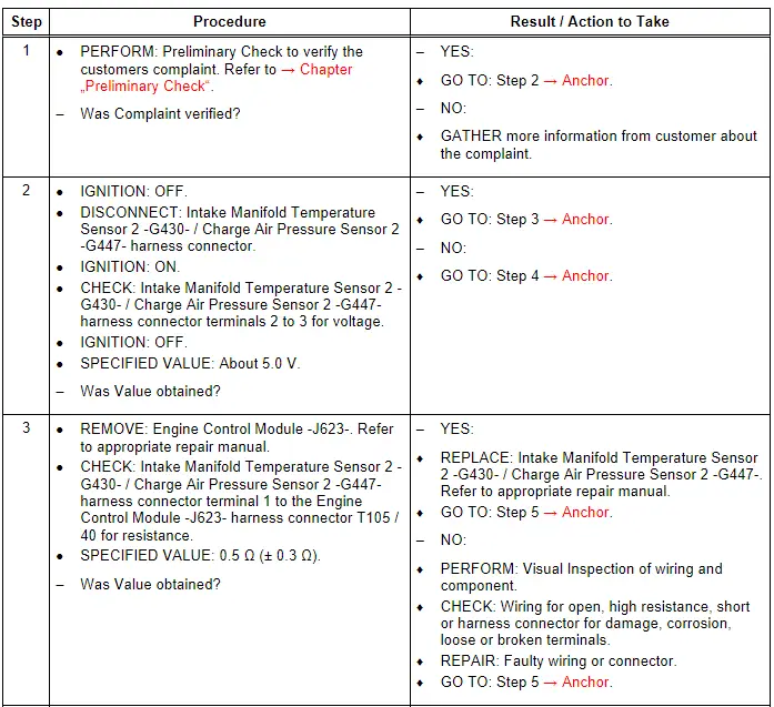
Charge Air Pressure Sensor - G31- / Intake Manifold Temperature Sensor - G72-, Checking
General Description
The Intake Manifold Temperature Sensor 2 -G430- / Charge Air Pressure Sensor 2 -G447- is located in the inlet to the intake manifold. The Engine Control Module -J623- uses the sensor's signal to regulate the charge air pressure. There is no substitute function in the event of signal failure. In case of signal failure, charge air pressure regulation is shut off, which will lead to a significant reduction in engine output.
Special tools and workshop equipment required
- Multimeter.
- Wiring Diagram.
- Scan Tool.
Test requirements
- Fuses OK.
- Battery voltage OK.
- Switch OFF all electrical and electronic accessories.
- Vehicles with automatic transmission, ensure the selector lever position is in "P".
- Vehicles with manual transmission, ensure the shifter lever position is in "N" with the parking brake applied.
- Coolant temperature: ≥ 80º C.
- Observe all safety precautions: → Chapter "Safety Precautions".
- View clean working conditions: → Chapter "Clean Working Conditions".
- For Hybrid vehicles, refer to: → Chapter "High Voltage System General Warnings".
Test Procedure