Audi Q7: Component Location Overview - Components in Front Vehicle Interior
Component Location Overview - Components Inside Front Passenger Compartment, Left Side of Passenger Compartment
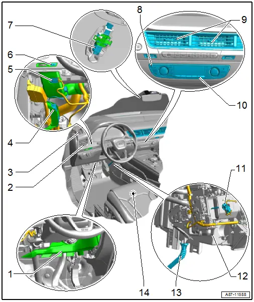
1 - Left Footwell Vent
- Overview. Refer to → Chapter "Overview - Air Routing and Air Distribution in Passenger Compartment, Front".
2 - Left Side Window Defroster Vent
3 - Left Instrument Panel Vent
- Removing and installing. Refer to → Body Interior; Rep. Gr.70; Instrument Panel; Instrument Panel Vent, Removing and Installing.
4 - Driver Side Ionizer -J1105-
- Refer to → Chapter "Driver Side Ionizer -J1105-, Removing and Installing"
- Not intended for all vehicles, only installed on specific vehicles with a "Mix" or "High" A/C system. Refer to → Wiring diagrams, Troubleshooting & Component locations.
- To check. Refer to Vehicle Diagnostic Tester in the "Guided Fault Finding" function
5 - Left Front Upper Body Vent Temperature Sensor -G385-
- To check. Refer to Vehicle Diagnostic Tester in the "Guided Fault Finding" function. Refer to → Wiring diagrams, Troubleshooting & Component locations.
- Removing and installing. Refer to → Chapter "Left Front Upper Body Vent Temperature Sensor -G385-, Removing and Installing".
6 - Driver Side Ionizer Button -E830-
- Installed in the left instrument panel vent trim
- Removing and installing. Refer to → Electrical Equipment; Rep. Gr.96; Controls; Buttons in Instrument Panel, Removing and Installing.
 Note
Note
- The driver side air ionization is only intended for certain vehicles with a "Mix" or "High" Air ionization and only for certain market specific vehicles. Refer to the Audi Sales Program.
- The Driver Side Ionizer Button -E830- and the Driver Side Ionizer -J1105- is always installed in the driver side air duct.
7 - Humidity Sensor -G355-
- There are different versions. Refer to the Parts Catalog.
- To check. Refer to Vehicle Diagnostic Tester in the "Guided Fault Finding" function. Refer to → Wiring diagrams, Troubleshooting & Component locations.
- The humidity sensor is integrated in the Rain/Light Recognition Sensor -G397- and cannot be replaced separately when faulty. Replacing. Refer to → Electrical Equipment; Rep. Gr.92; Windshield Wiper System; Rain/Light Recognition Sensor, Removing and Installing.
8 - Infrared Sensor
- The infrared sensor for the temperature and sunlight is integrated in the Front A/C Display Control Head -E87- and cannot be replaced separately. Replace. Refer to → Chapter "Front A/C Display Control Head -E87-, Removing and Installing".
- The sensor determines the temperature and sunlight on the Front A/C Display Control Head -E87-. It is permanently installed and cannot be replaced separately.
- A dirty infrared sensor leads to problems regulating the A/C system. Refer to Vehicle Diagnostic Tester in the "Guided Fault Finding" function.
9 - Center Vent in the Broadband Nozzle
- Closed on vehicles with a "Low" or "Mid" A/C system.
- Removing and installing. Refer to → Body Interior; Rep. Gr.70; Instrument Panel; Instrument Panel Vent, Removing and Installing.
10 - Front A/C Display Control Head -E87-
- Different versions (for vehicles with a "Low", "Mid", "Mix" or "High" A/C system with or without a seat heating/seat ventilation, depending on the production time period and vehicle equipment). Refer to the Parts Catalog for the allocation.
- Removing and installing. Refer to → Chapter "Front A/C Display Control Head -E87-, Removing and Installing".
- To check. Refer to Vehicle Diagnostic Tester in the "Guided Fault Finding" function. Refer to → Wiring diagrams, Troubleshooting & Component locations.
- Note the general information. Refer to → Chapter "General Information".
 Note
Note
- The buttons and knobs have LEDs that cannot be replaced individually.
- The function and indicator lamps in the buttons and in the knobs cannot be replaced separately.
- Pay attention to the correct allocation, coding, and adaptation of the Front A/C Display Control Head -E87- to the Front Information Display Control Head Control Module -J523-/Information Electronics Control Module 1 -J794-. Refer to the Parts Catalog and Vehicle Diagnostic Tester in the "Guided Fault Finding" function. If the allocation, coding or adaptation are incorrect, the A/C system functions cannot be displayed or selected in the MMI.
- Certain A/C system functions can be switched on and off via the MMI (Multi Media Interface) in the "A/C system" function under the "Car"/"Vehicle" menu. The A/C system control can also be influenced via the presets in the MMI (Multi Media Interface) under the "A/C system" function in the "Car"/"Vehicle" menu. Therefore, check the preset in the MMI first in the case there is a problem with these components. Refer to Infotainment/MMI Operating Instructions.
- Depending on the version of the control modules (Front A/C Display Control Head -E87- and Front Information Display Control Head Control Module -J523-) as well as the production period, additional functions can be switched on and off via these control modules. For more information, refer to the Operating Instructions and Infotainment/MMI Operating Instructions.
11 - Left Footwell Vent Temperature Sensor -G261-
- To check. Refer to Vehicle Diagnostic Tester in the "Guided Fault Finding" function
- Removing and installing. Refer to → Chapter "Left Footwell Vent Temperature Sensor -G261-, Removing and Installing".
12 - Heater and A/C Unit, Left Side
- Overview. Refer to → Chapter "Overview - Heater and A/C Unit".
- Removing and installing. Refer to → Chapter "Heater and A/C Unit, Removing and Installing".
13 - Left Condensation Water Drain (Driver Side)
- Refer to → Chapter "Condensation Water Drain, Removing and Installing"
14 - Left Front Seat
- Depending on the vehicle equipment level with seat heating, seat ventilation and massage function
- There are different versions. Refer to the Parts Catalog.
- Information about seat heating function. Refer to → Chapter "Front Seat Heating".
- Information about seat ventilation. Refer to → Chapter "Seat Ventilation".
- Information about the massage function. Refer to → Chapter "Seat Ventilation".
- Seat heating, servicing. Refer to → Body Interior; Rep. Gr.74; Front Seat Covers and Cushions; Overview - Seat Heating Element.
- Seat ventilation, servicing. Refer to → Body Interior; Rep. Gr.72; Front Seats; Component Location Overview - Electric and Electronic Components.
- Servicing the massage function. Refer to → Body Interior; Rep. Gr.72; Front Seat Pneumatic System; Overview - Pneumatic System.
Component Location Overview - Components Inside Front Passenger Compartment, Right Side of Passenger Compartment
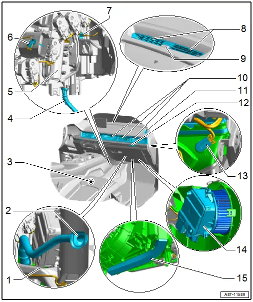
1 - Right Footwell Vent
- Overview. Refer to → Chapter "Overview - Air Routing and Air Distribution in Passenger Compartment, Front".
2 - Air Duct for Glove Compartment Cooling
- Not installed on all vehicles (optional equipment, depending on the vehicle version). Refer to → Chapter "Air Guide for Glove Compartment Cooling, Removing and Installing".
3 - Right Front Seat
- Depending on the vehicle equipment level with seat heating, seat ventilation and massage function
- There are different versions. Refer to the Parts Catalog.
- Information about seat heating function. Refer to → Chapter "Front Seat Heating".
- Information about seat ventilation. Refer to → Chapter "Seat Ventilation".
- Information about the massage function. Refer to → Chapter "Seat Ventilation".
- Seat heating, servicing. Refer to → Body Interior; Rep. Gr.74; Front Seat Covers and Cushions; Overview - Seat Heating Element.
- Seat ventilation, servicing. Refer to → Body Interior; Rep. Gr.72; Front Seats; Component Location Overview - Electric and Electronic Components.
- Servicing the massage function. Refer to → Body Interior; Rep. Gr.72; Front Seat Pneumatic System; Overview - Pneumatic System.
4 - Right Condensation Water Drain
- Checking. Refer to → Chapter "Condensation Water Drain, Checking".
- Removing and installing. Refer to → Chapter "Condensation Water Drain, Removing and Installing".
5 - Heater and A/C Unit, Right Side
- Overview. Refer to → Chapter "Overview - Heater and A/C Unit".
- Removing and installing. Refer to → Chapter "Heater and A/C Unit, Removing and Installing".
6 - Right Footwell Vent Temperature Sensor -G262-
- To check. Refer to Vehicle Diagnostic Tester in the "Guided Fault Finding" function
- Removing and installing. Refer to → Chapter "Right Footwell Vent Temperature Sensor -G262-, Removing and Installing".
7 - Evaporator Vent Temperature Sensor -G263-
- To check. Refer to Vehicle Diagnostic Tester in the "Guided Fault Finding" function. Refer to → Wiring diagrams, Troubleshooting & Component locations.
- Removing and installing. Refer to → Chapter "Evaporator Vent Temperature Sensor -G263-, Removing and Installing".
8 - Windshield Defroster Vent
- Removing and installing. Refer to → Body Interior; Rep. Gr.70; Instrument Panel; Front Center Defroster Vent, Removing and Installing.
9 - Sunlight Photo Sensor -G107-
- Removing and installing. Refer to → Chapter "Sunlight Photo Sensor -G107-, Removing and Installing".
- Check. Refer to Vehicle Diagnostic Tester in the "Guided Fault Finding" Function
10 - Broadband Nozzle
- There are different versions. Allocation. Refer to the Parts Catalog.
- Removing and installing. Refer to → Body Interior; Rep. Gr.70; Instrument Panel; Instrument Panel Vent, Removing and Installing.
11 - Right Side Window Defroster Vent
- Overview. Refer to → Chapter "Overview - Air Routing and Air Distribution in Passenger Compartment, Front".
12 - Instrument Panel Vent Button -E815-
- Only on vehicles with a "Mix" or "High" A/C system
- Removing and installing. Refer to → Electrical Equipment; Rep. Gr.96; Controls; Buttons in Instrument Panel, Removing and Installing.
13 - Right Front Upper Body Vent Temperature Sensor -G386-
- To check. Refer to Vehicle Diagnostic Tester"Guided Fault Finding" function. Refer to → Wiring diagrams, Troubleshooting & Component locations.
- Removing and installing. Refer to → Chapter "Right Front Upper Body Vent Temperature Sensor -G386-, Removing and Installing".
14 - Fresh Air Blower -V2- with Fresh Air Blower Control Module -J126-
- There are different versions. Refer to the Parts Catalog.
- Check. Refer to Vehicle Diagnostic Tester in the "Guided Fault Finding" function
- Removing and installing. Refer to → Chapter "Fresh Air Blower -V2- with Fresh Air Blower Control Module -J126-, Removing and Installing".
15 - Dust and Pollen Filter (with or without Activated Charcoal Filter Element)
- Follow the replacement intervals. Refer to the →Maintenance Intervals; Rep. Gr.03.
- There are different versions. Allocation. Refer to the Parts Catalog.
- With activated charcoal filter element. There is an Air Quality Sensor -G238- installed on these vehicles. Refer to → Chapter "Dust and Pollen Filter with Activated Charcoal Insert, Element Information".
- Removing and installing. Refer to → Chapter "Dust and Pollen Filter, Removing and Installing".

