Audi Q7: System Overview - Refrigerant Circuit
System Overview - Refrigerant Circuit without Rear Heater and A/C Unit
 Note
Note
Depending on vehicle equipment, there are different versions of the A/C system for the Audi Q7. Make sure to use the correct version and pay attention to the allocation of different components. Refer to → Chapter "A/C System Versions" and Parts Catalog.
"Low"Mid" or "Mix" A/C system (A/C compressor, condenser and inner heat exchanger)
HD = high pressure side
ND = low pressure side
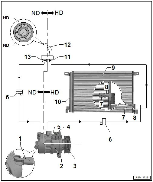
1 - A/C Compressor Regulator Valve -N280-
- Checking. Refer to → Chapter "A/C Compressor Regulator Valve -N280-, Checking Switch-On Signal".
2 - A/C Compressor
- Overview. Refer to → Chapter "Overview - A/C Compressor Power Unit".
3 - A/C Compressor Belt Pulley
- Replace the belt pulley. Refer to → Chapter "Overview - Belt Pulley".
 Note
Note
With or without the A/C Clutch -N25- depending on the engine and the A/C compressor.
4 - Oil Drain Plug
 Caution
Danger due to refrigerant coming out under pressure.
Danger of frost bite to skin and other parts of the body.
Only remove on an empty refrigerant circuit.
5 - Pressure Relief Valve
 Caution
Danger due to refrigerant coming out under pressure when there is a faulty valve.
Danger of frost bite to skin and other parts of the body.
Only remove when the refrigerant circuit is empty. The connection does not have a valve.
6 - Connection in Refrigerant Line
- Depending on the version of the vehicle and the engine, these connection points may be present at different locations on the refrigerant lines.
 Caution
Danger due to refrigerant coming out under pressure.
Danger of frost bite to skin and other parts of the body.
Only loosen the connection point bolts when the refrigerant circuit is empty.
7 - High Pressure Sensor -G65-
- Removing and installing. Refer to → Chapter "High Pressure Sensor -G65-, Removing and Installing".
- Checking. Refer to → Chapter "High Pressure Sensor -G65-, Checking".
8 - Connection with Valve
9 - Condenser
- Overview. Refer to → Chapter "Overview - Refrigerant Circuit Components".
10 - Receiver/Dryer (of the Condenser with Dryer Cartridge)
- The receiver/dryer is integrated in the condenser.
- Overview. Refer to → Chapter "Overview - Refrigerant Circuit Components".
11 - Refrigerant Line Connection - Low Pressure Side
- Installed in the area of the left headlamp under the fender
12 - Refrigerant Line with Inner Heat Exchanger
- Installed in the area under the left fender
- In this refrigerant line, the liquid warm refrigerant flowing on the high pressure side releases energy into the vaporous cold refrigerant flowing on the low pressure side. This increases the cooling efficiency of the A/C system.
13 - Refrigerant Line Connection - High Pressure Side
- Installed in the area of the left headlamp under the fender
"Low"Mid" or "Mix" A/C system (inner heater core, expansion valve, evaporator, and service connection)
HD = high pressure side
ND = low pressure side
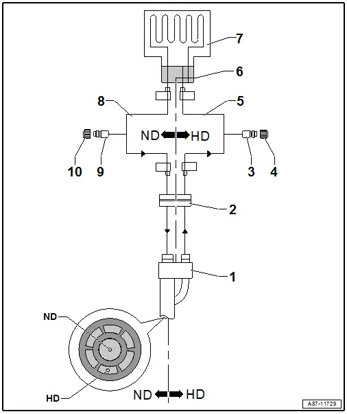
1 - Refrigerant Line with Inner Heat Exchanger
- Installed in the area under the left fender
- In this refrigerant line, the liquid warm refrigerant flowing on the high pressure side releases energy into the vaporous cold refrigerant flowing on the low pressure side. This increases the cooling efficiency of the A/C system.
2 - Refrigerant Line Openings
- From the area under the left fender in the plenum chamber
- Version without outlets to a second evaporator
3 - High Pressure Side Service Connection
- For measuring, discharging and charging
- Depending on the vehicle version installed in the left plenum chamber (near the brake fluid reservoir) under the plenum chamber or in the left engine compartment
 Caution
Danger due to refrigerant coming out under pressure when there is a faulty valve in the refrigerant circuit.
Danger of frost bite to skin and other parts of the body.
Only remove when the refrigerant circuit is empty. The connection does not have a valve. Refer to → Refrigerant R134a Servicing; Rep. Gr.87; A/C System, General Information.
4 - Closure Cap
- With seal
- Always screw on
5 - Refrigerant Line to High Pressure Side Expansion Valve
6 - Front Expansion Valve
- Overview. Refer to → Chapter "Overview - Refrigerant Lines in Plenum Chamber and Front Expansion Valve".
7 - Evaporator
- In the front heater and A/C unit (installed under the instrument panel)
8 - Refrigerant Line to Low Pressure Side Expansion Valve
9 - Low Pressure Side Service Connection
- For measuring, discharging and charging
- Depending on the vehicle version installed in the left plenum chamber (near the brake fluid reservoir) under the plenum chamber or in the left engine compartment
 Caution
Danger due to refrigerant coming out under pressure when there is a faulty valve in the refrigerant circuit.
Danger of frost bite to skin and other parts of the body.
Only remove when the refrigerant circuit is empty. The connection does not have a valve. Refer to → Refrigerant R134a Servicing; Rep. Gr.87; A/C System, General Information.
10 - Closure Cap
- With seal
- Always screw on
System Overview - Refrigerant Circuit with Rear Heater and A/C Unit
 Note
Note
Depending on vehicle equipment, there are different versions of the A/C system for the Audi Q7. Make sure to use the correct version and pay attention to the allocation of different components. Refer to → Chapter "A/C System Versions" and Parts Catalog.
"High" A/C system (A/C compressor, condenser and inner heat exchanger)
HD = High Pressure Side
ND = Low Pressure Side

1 - A/C Compressor Regulator Valve -N280-
- Checking. Refer to → Chapter "A/C Compressor Regulator Valve -N280-, Checking Switch-On Signal".
2 - A/C Compressor
- Overview. Refer to → Chapter "Overview - A/C Compressor Power Unit".
3 - A/C Compressor Belt Pulley
- Replace the belt pulley. Refer to → Chapter "Overview - Belt Pulley".
 Note
Note
With or without the A/C Clutch -N25- depending on the engine and the A/C compressor.
4 - Oil Drain Plug
 Caution
Danger due to refrigerant coming out under pressure.
Danger of frost bite to skin and other parts of the body.
Only remove on an empty refrigerant circuit.
5 - Pressure Relief Valve
 Caution
Danger due to refrigerant coming out under pressure when there is a faulty valve.
Danger of frost bite to skin and other parts of the body.
Only remove when the refrigerant circuit is empty. The connection does not have a valve.
6 - Connection in Refrigerant Line
- Depending on the version of the vehicle and the engine, these connection points may be present at different locations on the refrigerant lines.
7 - High Pressure Sensor -G65-
- Removing and installing. Refer to → Chapter "High Pressure Sensor -G65-, Removing and Installing".
- Checking. Refer to → Chapter "High Pressure Sensor -G65-, Checking".
8 - Connection with Valve
9 - Condenser
- Overview. Refer to → Chapter "Overview - Refrigerant Circuit Components".
10 - Receiver/Dryer (of the Condenser with Dryer Cartridge)
- The receiver/dryer is integrated in the condenser.
- Overview. Refer to → Chapter "Overview - Refrigerant Circuit Components".
11 - Refrigerant Line Connection - Low Pressure Side
- Installed in the area of the left headlamp under the fender
12 - Refrigerant Line with Inner Heat Exchanger
- Installed in the area under the left fender
- In this refrigerant line, the liquid warm refrigerant flowing on the high pressure side releases energy into the vaporous cold refrigerant flowing on the low pressure side. This increases the cooling efficiency of the A/C system.
13 - Refrigerant Line Connection - High Pressure Side
- Installed in the area of the left headlamp under the fender
"High" A/C system (inner heat exchanger, expansion valve evaporator and service connections)
HD = High Pressure Side
ND = Low Pressure Side
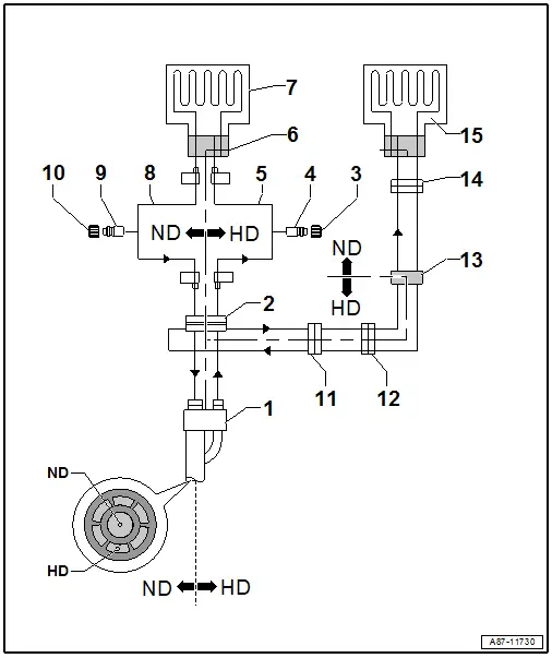
1 - Refrigerant Line with Inner Heat Exchanger
- Installed in the area under the left fender
- In this refrigerant line, the liquid warm refrigerant flowing on the high pressure side releases energy into the vaporous cold refrigerant flowing on the low pressure side. This increases the cooling efficiency of the A/C system.
2 - Refrigerant Line Openings
- From the area under the left fender in the plenum chamber
- Version with entry way to a second evaporator
3 - Closure Cap
- With seal
- Always screw on
4 - High Pressure Side Service Connection
- For measuring, discharging and charging
- Depending on the vehicle version installed in the left plenum chamber (near the brake fluid reservoir) under the plenum chamber or in the left engine compartment
 Caution
Danger due to refrigerant coming out under pressure when there is a faulty valve in the refrigerant circuit.
Danger of frost bite to skin and other parts of the body.
Only remove when the refrigerant circuit is empty. The connection does not have a valve. Refer to → Refrigerant R134a Servicing; Rep. Gr.87; A/C System, General Information.
 Caution
Do not bend the refrigerant line when connecting the service coupling.
Counterhold on the refrigerant line when connecting the service coupling.
5 - Refrigerant Line to High Pressure Side Expansion Valve
6 - Front Expansion Valve
- Overview. Refer to → Chapter "Overview - Refrigerant Lines in Plenum Chamber and Front Expansion Valve".
7 - Evaporator
- In the front heater and A/C unit (installed under the instrument panel)
8 - Refrigerant Line to Low Pressure Side Expansion Valve
9 - Low Pressure Side Service Connection
- For measuring and discharging
- Depending on the vehicle version installed in the left plenum chamber (near the brake fluid reservoir) under the plenum chamber or in the left engine compartment
 Caution
Danger due to refrigerant coming out under pressure when there is a faulty valve in the refrigerant circuit.
Danger of frost bite to skin and other parts of the body.
Only remove when the refrigerant circuit is empty. The connection does not have a valve. Refer to → Refrigerant R134a Servicing; Rep. Gr.87; A/C System, General Information.
 Caution
Do not bend the refrigerant line when connecting the service coupling.
Counterhold on the refrigerant line when connecting the service coupling.
10 - Closure Cap
- With seal
- Always screw on
11 - Connection in Refrigerant Line to Evaporator in Rear Heater and A/C Unit
12 - Connection in Refrigerant Line to Evaporator in Rear Heater and A/C Unit
- On the underbody
- Overview. Refer to → Chapter "Overview - Expansion Valve and Refrigerant Lines to Rear Heater and A/C Unit".
13 - Rear Expansion Valve
- Overview. Refer to → Chapter "Overview - Expansion Valve and Refrigerant Lines to Rear Heater and A/C Unit".
14 - Refrigerant Line Connection to Evaporator in Rear Heater and A/C Unit
- On the underbody at the bottom of the center console
15 - Rear Evaporator
- Installed in the heater and A/C unit (the heater and A/C unit is installed in the center console)

