Audi Q7: Component Location Overview - Components Inside Rear Passenger Compartment
Component Location Overview - Components Inside Left Rear Passenger Compartment
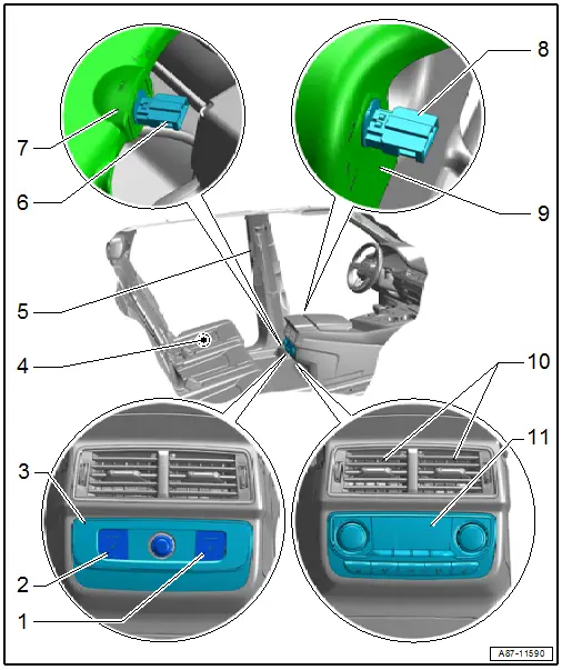
1 - Right Seat Heating Button -E654-
- Installed only in vehicles with a "Low" A/C system (without a Rear A/C Display Control Head -E265-).
- Check. Refer to Vehicle Diagnostic Tester in the "Guided Fault Finding" function for the Vehicle Electrical System Control Module -J519-.
- Servicing the seat heating. Refer to → Body Interior; Rep. Gr.72; Rear Seats.
- Notes about seat heating. Refer to → Chapter "Seat Heating".
 Note
Note
These switches are currently not OBD-capable. The seat heating is only activated when it is enabled by the Vehicle Electrical System Control Module -J519- accordingly.
2 - Left Seat Heating Button -E653-
- Installed only in vehicles with a "Low" A/C system (without a Rear A/C Display Control Head -E265-).
- Check. Refer to Vehicle Diagnostic Tester in the "Guided Fault Finding" function for the Vehicle Electrical System Control Module -J519-.
- Servicing the seat heating. Refer to → Body Interior; Rep. Gr.72; Rear Seats.
- Notes about seat heating. Refer to → Chapter "Seat Heating".
 Note
Note
These switches are currently not OBD-capable. The seat heating is only activated when it is enabled by the Vehicle Electrical System Control Module -J519- accordingly.
3 - Trim
- For vehicles with a "Low" A/C system (without a Rear A/C Display Control Head -E265-).
4 - Left Rear Seat/Rear Bench Seat
- Equipment level with seat heating
- There are different versions. Refer to the Parts Catalog.
- Information about seat heating function. Refer to → Chapter "Seat Heating".
- Servicing the seat heating. Refer to → Body Interior; Rep. Gr.72; Rear Seats.
5 - Left B-Pillar Vent
- Only in the "Mid", "Mix" or "High" A/C system version
- Removing and installing. Refer to → Body Interior; Rep. Gr.70; Vehicle Interior Trim Panels; B-Pillar Trim Panel, Removing and Installing.
6 - Left Rear Upper Body Vent Temperature Sensor -G635-
- Only "High" A/C system version
- To check. Refer to Vehicle Diagnostic Tester in the "Guided Fault Finding" function
- Removing and installing. Refer to → Chapter "Left Rear Upper Body Vent Temperature Sensor -G635-, Removing and Installing".
7 - Air Duct
- For the B-pillar vent
8 - Left Rear Footwell Vent Temperature Sensor -G637-
- Only "High" A/C system version
- To check. Refer to Vehicle Diagnostic Tester in the "Guided Fault Finding" function
- Removing and installing. Refer to → Chapter "Left Rear Footwell Vent Temperature Sensor -G637-, Removing and Installing".
9 - Air Duct
- For the rear footwell vent
10 - Vent in Rear Center Console
- Removing and installing. Refer to → Body Interior; Rep. Gr.68; Center Console; Center Console, Removing and Installing.
11 - Rear A/C Display Control Head -E265-
- Only the "Mid", "Mix" or "High" A/C system version
- There are different versions. Allocation. Refer to the Parts Catalog.
- To check. Refer to Vehicle Diagnostic Tester in the "Guided Fault Finding" function
- Removing and installing. Refer to → Chapter "Display Control Head, Removing and Installing".
- Notes. Refer to → Chapter "Rear A/C Display Control Head - E265-, Removing and Installing, Mid or Mix A/C System" and → Chapter "Rear A/C Display Control Head -E265-, Removing and Installing, High A/C System".
 Note
Note
- There is currently no child lock-out feature planned for the Rear A/C Display Control Head -E265- (introduction not yet finalized). If the child safety system for the Rear A/C Display Control Head -E265- is offered in the future and is active in the vehicle, the setting of the rear A/C system and the seat heating cannot be changed by the Rear A/C Display Control Head -E265- (when a button or knob is operated, three lines appear in both displays). The settings can then only be modified via the Front A/C Display Control Head -E87- and the MMI Terminal. Refer to the Operating Instructions.
- On a vehicle with a "Mid" or "Mix" A/C system the Rear A/C Display Control Head -E265- exchanges information via the LIN bus with the Front A/C Display Control Head -E87-. Refer to Vehicle Diagnostic Tester in the "Guided Fault Finding" function and refer to → Wiring diagrams, Troubleshooting & Component locations.
- On a vehicle with a "High" A/C system the Rear A/C Display Control Head -E265- exchanges information via the data bus with the Front A/C Display Control Head -E87-. Refer to Vehicle Diagnostic Tester in the "Guided Fault Finding" function and refer to → Wiring diagrams, Troubleshooting & Component locations.
- When replacing the Rear A/C Display Control Head -E265-, ensure correct allocation with respect to the Front A/C Display Control Head -E87-. If the allocation is incorrect, various functions of the rear A/C system, for example, may not be able to be displayed and selected. Refer to the Parts Catalog.
- Certain A/C system functions can be switched on and off via the MMI (Multi Media Interface) in the "A/C system" function under the "Car"/"Vehicle" menu. The A/C system control can also be influenced via the presets in the MMI (Multi Media Interface) under the "A/C system" function in the "Car"/"Vehicle" menu. Therefore, check the preset in the MMI first in the case there is a problem with these components. Refer to Infotainment/MMI Operating Instructions.
Component Location Overview - Components Inside Right Rear Passenger Compartment
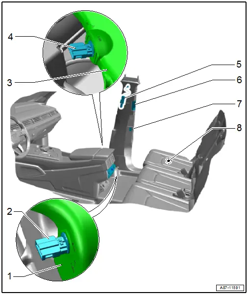
1 - Air Duct
- For the rear footwell vent
2 - Right Rear Footwell Vent Temperature Sensor -G638-
- Only "High" A/C system version
- To check. Refer to Vehicle Diagnostic Tester in the "Guided Fault Finding" function
- Removing and installing. Refer to → Chapter "Right Rear Footwell Vent Temperature Sensor -G638-, Removing and Installing".
3 - Air Duct
- For the B-pillar vent
4 - Right Rear Upper Body Vent Temperature Sensor -G636-
- Only "High" A/C system version
- To check. Refer to Vehicle Diagnostic Tester in the "Guided Fault Finding" function
- Removing and installing. Refer to → Chapter "Right Rear Upper Body Vent Temperature Sensor -G636-, Removing and Installing".
5 - Front Passenger Side Rear Ionizer -J1108-
- Versions for specific countries
- On the air duct to the B-pillar vent
- Removing and installing. Refer to → Chapter "Front Passenger Side Rear Ionizer -J1108-, Removing and Installing".
 Note
Note
The Front Passenger Side Rear Ionizer Button -E833- and the Front Passenger Side Rear Ionizer -J1108- are always installed behind the rear passenger seat on the B-pillar.
6 - Right B-Pillar Vent
- Removing and installing. Refer to → Body Interior; Rep. Gr.70; Vehicle Interior Trim Panels; B-Pillar Trim Panel, Removing and Installing.
7 - Front Passenger Side Rear Ionizer Button -E833-
- Versions for specific countries
- Only "High" A/C system version
- Removing and installing. Refer to → Electrical Equipment; Rep. Gr.96; Controls; Component Location Overview - Controls in Center Console.
 Note
Note
The Front Passenger Side Rear Ionizer Button -E833- and the Front Passenger Side Rear Ionizer -J1108- are always installed behind the rear passenger seat on the B-pillar.
8 - Right Rear Seat/Rear Bench Seat
- Equipment level with seat heating
- There are different versions. Refer to the Parts Catalog.
- Information about seat heating function. Refer to → Chapter "Seat Heating".
- Servicing the seat heating. Refer to → Body Interior; Rep. Gr.72; Rear Seats.

