Audi Q7: Overview - Refrigerant Circuit Components
Overview - A/C Compressor and Condenser
 Caution
Danger due to refrigerant coming out under pressure.
Danger of frost bite to skin and other parts of the body.
Only loosen the connection point bolts when the refrigerant circuit is empty.
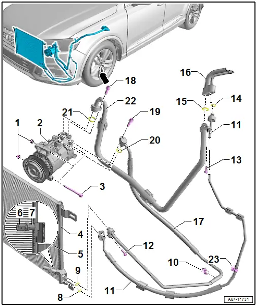
1 - Alignment Sleeve
2 - A/C Compressor
- Overview. Refer to → Chapter "Overview - A/C Compressor Power Unit".
 Note
Note
This illustration shows the installation position on a vehicle with a 6-cylinder engine.
3 - Bolt
- Tightening specification. Refer to → Chapter "Overview - A/C Compressor Power Unit".
4 - Left Manifold on the Condenser
5 - Condenser (with Receiver/Dryer)
- There are different versions. Refer to the Parts Catalog.
- Refrigerant lines, removing and installing. Refer to → Chapter "Refrigerant Lines, Disconnecting and Connecting at Condenser".
- Removing and installing. Refer to → Chapter "Condenser, Removing and Installing".
- Receiver/dryer is a component of the condenser. Refer to → Chapter "Overview - Condenser, Dryer Bag/Dryer Cartridge".
- Different versions of the receiver/dryer. Refer to the Parts Catalog.
- Dryer from the receiver/dryer, removing and installing. Refer to → Chapter "Dryer Cartridge, Removing and Installing, from Receiver/Dryer on Condenser".
6 - High Pressure Sensor -G65-
- Refer to → Chapter "High Pressure Sensor -G65-, Checking, Removing and Installing"
7 - Connection with Valve
8 - O-Ring
- To replace. Refer to → Chapter "Refrigerant Circuit Seals" and to the Parts Catalog for the correct version.
- Lubricate lightly with refrigerant oil before installing
9 - O-Ring
- To replace. Refer to → Chapter "Refrigerant Circuit Seals" and to the Parts Catalog for the correct version.
- Lubricate lightly with refrigerant oil before installing
10 - Bracket
- There are different versions. Refer to the Parts Catalog.
- Not always present
11 - High Pressure Side Refrigerant Line
- From the condenser to the inner heat exchanger
- There are different versions. Refer to the Parts Catalog.
- Removing and installing. Refer to → Chapter "Refrigerant Lines, Disconnecting and Connecting at Condenser".
- Removing and installing from Inner Heat Exchanger. Refer to → Chapter "Connection Points of Refrigerant Lines, Loosening and Assembling".
12 - Bolt
- 9 Nm
13 - Bolt
- 9 Nm
14 - O-Ring
- To replace. Refer to → Chapter "Refrigerant Circuit Seals" and to the Parts Catalog for the correct version.
- Lubricate lightly with refrigerant oil before installing
15 - O-Ring
- To replace. Refer to → Chapter "Refrigerant Circuit Seals" and to the Parts Catalog for the correct version.
- Lubricate lightly with refrigerant oil before installing
16 - Refrigerant Line with Inner Heat Exchanger
- Overview. Refer to → Chapter "Overview - Inner Heat Exchanger and Components under Front Left Fender".
- In this refrigerant line, the liquid warm refrigerant flowing on the high pressure side releases energy into the vaporous cold refrigerant flowing on the low pressure side. This increases the cooling efficiency of the A/C system.
- Removing and installing. Refer to → Chapter "Refrigerant Lines with Inner Heat Exchanger, Removing and Installing".
17 - High Pressure Side Refrigerant Line
- From A/C compressor to condenser
- There are different versions. Refer to the Parts Catalog.
- Removing and installing from the A/C compressor. Refer to → Chapter "Overview - A/C Compressor and Condenser".
- Removing and installing from the condenser. Refer to → Chapter "Refrigerant Lines, Disconnecting and Connecting at Condenser".
18 - Bolt
- 9 Nm
19 - Bolt
- 9 Nm
20 - O-Ring
- To replace. Refer to → Chapter "Refrigerant Circuit Seals" and to the Parts Catalog for the correct version.
- Lubricate lightly with refrigerant oil before installing
21 - O-Ring
- To replace. Refer to → Chapter "Refrigerant Circuit Seals" and to the Parts Catalog for the correct version.
- Lubricate lightly with refrigerant oil before installing
22 - Low Pressure Side Refrigerant Line
- From the inner heat exchanger to the A/C compressor
- There are different versions. Refer to the Parts Catalog.
- Removing and installing from the A/C compressor. Refer to → Chapter "Overview - A/C Compressor and Condenser".
- Removing and installing from Inner Heat Exchanger. Refer to → Chapter "Connection Points of Refrigerant Lines, Loosening and Assembling".
Overview - Condenser, Dryer Bag/Dryer Cartridge
 Caution
Danger due to refrigerant coming out under pressure.
Danger of frost bite to skin and other parts of the body.
Only loosen the connection point bolts when the refrigerant circuit is empty.
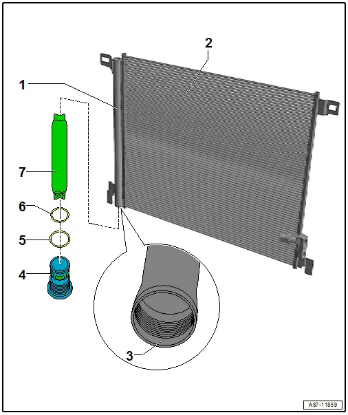
1 - Receiver/Dryer
- Receiver/dryer is a component of the condenser
- There are different versions. Refer to the Parts Catalog.
- Dryer bag, removing and installing. Refer to → Chapter "Dryer Cartridge, Removing and Installing, from Receiver/Dryer on Condenser".
2 - Condenser
- There are different versions. Refer to the Parts Catalog.
- Refrigerant lines, removing and installing. Refer to → Chapter "Refrigerant Lines, Disconnecting and Connecting at Condenser".
- Removing and installing. Refer to → Chapter "Condenser, Removing and Installing".
3 - Sealing Surfaces in the Receiver/Dryer
- Check for contamination and damage
 Note
Note
Even slight damage (a scratch) or a little bit of dirt (a hair) can cause leakage at a connection.
4 - Plug with Filter Element
- Replace after removing.
- Plug tightening specification 2 Nm
- Removing and installing. Refer to → Chapter "Dryer Cartridge, Removing and Installing, from Receiver/Dryer on Condenser".
 Caution
Danger due to refrigerant coming out under pressure.
Danger of frost bite to skin and other parts of the body.
Only loosen the bolts when the refrigerant circuit is empty.
 Note
Note
Check the filter element and if necessary clean the refrigerant circuit. Refer to → Refrigerant R134a Servicing; Rep. Gr.87; A/C System, General Information.
5 - O-Ring
- Replace after removing; version. Refer to the Parts Catalog.
- Coat with refrigerant oil before installing. Refer to → Chapter "Refrigerant Circuit Seals".
6 - O-Ring
- Replace after removing; version. Refer to the Parts Catalog.
- Coat with refrigerant oil before installing. Refer to → Chapter "Refrigerant Circuit Seals".
7 - Dryer Bag
- There are different versions. Refer to the Parts Catalog.
- Removing and installing. Refer to → Chapter "Dryer Cartridge, Removing and Installing, from Receiver/Dryer on Condenser".
Overview - Inner Heat Exchanger and Components under Front Left Fender
 Caution
Danger due to refrigerant coming out under pressure.
Danger of frost bite to skin and other parts of the body.
Only loosen the connection point bolts when the refrigerant circuit is empty.
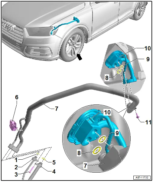
1 - O-Ring
- Replace after removing; version. Refer to the Parts Catalog.
- Coat with refrigerant oil before installing. Refer to → Chapter "Refrigerant Circuit Seals".
2 - High Pressure Side Refrigerant Line
- From the condenser to the inner heat exchanger
- There are different versions. Refer to the Parts Catalog.
- Removing and installing. Refer to → Chapter "Refrigerant Lines, Disconnecting and Connecting at Condenser".
- Removing and installing from Inner Heat Exchanger. Refer to → Chapter "Connection Points of Refrigerant Lines, Loosening and Assembling".
3 - Bolt
- 9 Nm
4 - Low Pressure Side Refrigerant Line
- From the inner heat exchanger to the A/C compressor
- There are different versions. Refer to the Parts Catalog.
- Removing and installing from the A/C compressor. Refer to → Chapter "Overview - A/C Compressor and Condenser".
- Removing and installing from inner heat exchanger. Refer to → Chapter "Connection Points of Refrigerant Lines, Loosening and Assembling".
5 - O-Ring
- Replace after removing; version. Refer to the Parts Catalog.
- Coat with refrigerant oil before installing. Refer to → Chapter "Refrigerant Circuit Seals".
6 - Inner Heat Exchanger Bracket
- There are different versions. Refer to the Parts Catalog.
7 - Refrigerant Line with Inner Heat Exchanger
- In this refrigerant line, the liquid warm refrigerant flowing on the high pressure side releases energy into the vaporous cold refrigerant flowing on the low pressure side. This increases the cooling efficiency of the A/C system.
- Removing and installing. Refer to → Chapter "Refrigerant Lines with Inner Heat Exchanger, Removing and Installing".
8 - O-Ring
- Replace after removing; version. Refer to the Parts Catalog.
- Coat with refrigerant oil before installing. Refer to → Chapter "Refrigerant Circuit Seals".
9 - O-Ring
- Replace after removing; version. Refer to the Parts Catalog.
- Coat with refrigerant oil before installing. Refer to → Chapter "Refrigerant Circuit Seals".
10 - Pass-Through for Refrigerant Lines in the Plenum Chamber
- There are different versions. Refer to the Parts Catalog.
- The illustration shows the version of vehicles without a second evaporator (with a "Low"Mid" or "Mix" A/C system)
- Version for a vehicle with a second evaporator (a "High" A/C system). Refer to → Chapter "Overview - Expansion Valve and Refrigerant Lines to Rear Heater and A/C Unit".
- Removing and installing. Refer to → Chapter "Plenum Chamber Refrigerant Line Pass-Through, Removing and Installing".
11 - Bolt
- 9 Nm
 Note
Note
- Depending on vehicle equipment, there are different versions of the A/C system for the Audi Q7. Make sure to use the correct version and pay attention to the allocation of different components. Refer to → Chapter "A/C System Versions" and Parts Catalog.
- Refer to → Chapter "Low A/C System Version"
- Refer to → Chapter "Mid A/C System Version"
- Refer to → Chapter "Mix A/C System Version"
- Refer to → Chapter "High A/C System Version"
Overview - Refrigerant Lines in Plenum Chamber and Front Expansion Valve
 Caution
Danger due to refrigerant coming out under pressure.
Danger of frost bite to skin and other parts of the body.
Only loosen the connection point bolts when the refrigerant circuit is empty.
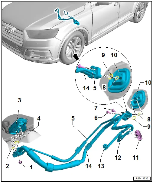
1 - Nut
- 9 Nm
- Instead of a nut on an expansion valve without a threaded pin, a bolt can also be installed on the expansion valve. Refer to the Parts Catalog.
2 - O-Ring
- Replace after removing; version. Refer to the Parts Catalog.
- Coat with refrigerant oil before installing. Refer to → Chapter "Refrigerant Circuit Seals".
3 - Front Expansion Valve
- There are different versions. Refer to the Parts Catalog.
- Refrigerant line, disconnecting and connecting. Refer to → Chapter "Refrigerant Lines, Disconnecting from Front Expansion Valve and Reconnecting".
- Removing and installing. Refer to → Chapter "Front Expansion Valve, Removing and Installing".
- With threaded pin on the expansion valve. Refer to the Parts Catalog.
 Note
Note
On an expansion valve without a threaded pin the refrigerant lines can also be secured with a bolt.
4 - O-Ring
- Replace after removing; version. Refer to the Parts Catalog.
- Coat with refrigerant oil before installing. Refer to → Chapter "Refrigerant Circuit Seals".
5 - Refrigerant Line - High Pressure Side
- With high pressure side service connection
- To the expansion valve from the openings for the refrigerant lines (from the area under the left fender)
- Removing and installing. Refer to → Chapter "Refrigerant Lines in Plenum Chamber, Removing and Installing".
6 - Bolt
- 9 Nm
7 - Bolt
- 9 Nm
8 - O-Ring
- To replace. Refer to → Chapter "Refrigerant Circuit Seals" and to the Parts Catalog for the correct version.
- Lubricate lightly with refrigerant oil before installing
9 - O-Ring
- To replace. Refer to → Chapter "Refrigerant Circuit Seals" and to the Parts Catalog for the correct version.
- Lubricate lightly with refrigerant oil before installing
10 - Pass-Through for Refrigerant Lines in the Plenum Chamber
- There are different versions. Refer to the Parts Catalog.
- The illustration shows the version of vehicles without a second evaporator (with a "Low"Mid" or "Mix" A/C system)
- Version for a vehicle with a second evaporator ("High" A/C system). Refer to → Chapter "Overview - Expansion Valve and Refrigerant Lines to Rear Heater and A/C Unit".
- Removing and installing. Refer to → Chapter "Plenum Chamber Refrigerant Line Pass-Through, Removing and Installing".
11 - Bracket for Refrigerant Lines
- There are different versions. Refer to the Parts Catalog.
12 - Service Connection - Low Pressure Side
- For measuring and discharging
- Depending on the vehicle version installed in the left plenum chamber (near the brake fluid reservoir, as shown here) under the plenum chamber or in the left engine compartment
- Cap with seal, always install
- Evacuating and charging valve, removing and installing. Refer to → Chapter "Evacuating and Charging Valve, Removing and Installing, Low and High Pressure Side".
 Caution
Danger due to refrigerant coming out under pressure when there is a faulty valve in the refrigerant circuit.
Danger of frost bite to skin and other parts of the body.
Only remove when the refrigerant circuit is empty. The connection does not have a valve. Refer to → Refrigerant R134a Servicing; Rep. Gr.87; A/C System, General Information.
 Caution
Do not bend the refrigerant line when connecting the service coupling.
Counterhold on the refrigerant line when connecting the service coupling.
13 - High Pressure Side Service Connection
- For measuring, discharging and charging
- Depending on the vehicle version installed in the left plenum chamber (near the brake fluid reservoir, as shown here) under the plenum chamber or in the left engine compartment
- Cap with seal, always install
- Evacuating and charging valve, removing and installing. Refer to → Chapter "Evacuating and Charging Valve, Removing and Installing, Low and High Pressure Side".
 Caution
Danger due to refrigerant coming out under pressure when there is a faulty valve in the refrigerant circuit.
Danger of frost bite to skin and other parts of the body.
Only remove when the refrigerant circuit is empty. The connection does not have a valve. Refer to → Refrigerant R134a Servicing; Rep. Gr.87; A/C System, General Information.
14 - Refrigerant Line - Low Pressure Side
- With low pressure side service connection
- From the expansion valve to the pass-through for the refrigerant lines (in the area under the left fender)
- Removing and installing. Refer to → Chapter "Refrigerant Lines in Plenum Chamber, Removing and Installing".
Overview - Expansion Valve and Refrigerant Lines to Rear Heater and A/C Unit
 Caution
Danger due to refrigerant coming out under pressure.
Danger of frost bite to skin and other parts of the body.
Only loosen the connection point bolts when the refrigerant circuit is empty.
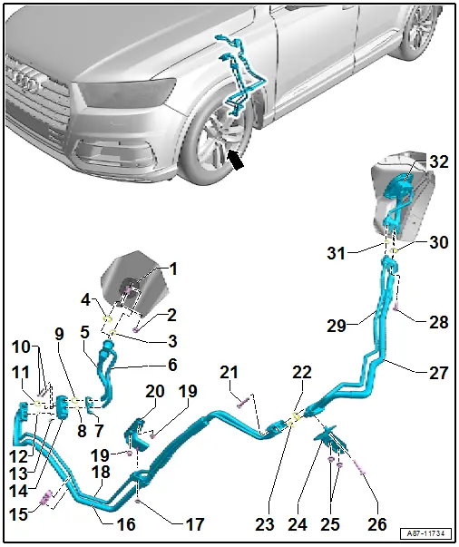
1 - Pass-Through for the Refrigerant Lines in the Vehicle Interior
- To evaporator in rear heater and a/c unit
- Removing and installing. Refer to → Chapter "Heater and A/C Unit, Removing and Installing, High A/C System".
2 - Nut
- 9 Nm
- To the threaded pin on the refrigerant line bracket on the evaporator in the rear heater and A/C unit
3 - O-Ring
- To replace. Refer to → Chapter "Refrigerant Circuit Seals" and to the Parts Catalog for the correct version.
- Lubricate lightly with refrigerant oil before installing
4 - O-Ring
- To replace. Refer to → Chapter "Refrigerant Circuit Seals" and to the Parts Catalog for the correct version.
- Lubricate lightly with refrigerant oil before installing
5 - Refrigerant Line - Low Pressure Side
- On the underbody (vehicle floor) in the area of the center tunnel
- From the refrigerant line opening in the vehicle interior to the expansion valve
- Removing and installing on the rear expansion valve. Refer to → Chapter "Refrigerant Lines, Removing and Installing, from Connection Point to Rear Expansion Valve".
- Removing and installing. Refer to → Chapter "Connection Points of Refrigerant Lines, Loosening and Assembling".
6 - Refrigerant Line - Low Pressure Side
- On the underbody (vehicle floor) in the area of the center tunnel
- From the expansion valve to the refrigerant line opening in the vehicle interior
- Removing and installing on the rear expansion valve. Refer to → Chapter "Refrigerant Lines, Removing and Installing, from Connection Point to Rear Expansion Valve".
- Removing and installing. Refer to → Chapter "Connection Points of Refrigerant Lines, Loosening and Assembling".
7 - Retaining Plate
8 - O-Ring
- To replace. Refer to → Chapter "Refrigerant Circuit Seals" and to the Parts Catalog for the correct version.
- Lubricate lightly with refrigerant oil before installing
9 - O-Ring
- To replace. Refer to → Chapter "Refrigerant Circuit Seals" and to the Parts Catalog for the correct version.
- Lubricate lightly with refrigerant oil before installing
10 - Bolt
- 9 Nm
- Removing and installing. Refer to → Chapter "Rear Expansion Valve, Removing and Installing ".
- Quantity: 2
11 - O-Ring
- To replace. Refer to → Chapter "Refrigerant Circuit Seals" and to the Parts Catalog for the correct version.
- Lubricate lightly with refrigerant oil before installing
12 - O-Ring
- To replace. Refer to → Chapter "Refrigerant Circuit Seals" and to the Parts Catalog for the correct version.
- Lubricate lightly with refrigerant oil before installing
13 - Nut
- 9 Nm
- Removing and installing. Refer to → Chapter "Rear Expansion Valve, Removing and Installing ".
14 - Rear Expansion Valve
- There are different versions. Refer to the Parts Catalog.
- Refrigerant line, disconnecting and connecting. Refer to → Chapter "Refrigerant Lines, Removing and Installing, from Rear Expansion Valve to Evaporator in Rear Heater and A/C Unit".
- Removing and installing. Refer to → Chapter "Rear Expansion Valve, Removing and Installing ".
15 - Bracket
- For the refrigerant lines on the underbody
16 - Refrigerant Line - Low Pressure Side
- On the underbody (vehicle floor)
- From the expansion valve
- Removing and installing on the rear expansion valve. Refer to → Chapter "Refrigerant Lines, Removing and Installing, from Connection Point to Rear Expansion Valve".
- Removing and installing. Refer to → Chapter "Connection Points of Refrigerant Lines, Loosening and Assembling".
17 - Nut
- 2 Nm
18 - Refrigerant Line - High Pressure Side
- On the underbody (vehicle floor)
- To the expansion valve
- Removing and installing on the rear expansion valve. Refer to → Chapter "Refrigerant Lines, Removing and Installing, from Connection Point to Rear Expansion Valve".
- Removing and installing. Refer to → Chapter "Connection Points of Refrigerant Lines, Loosening and Assembling".
19 - Nut
- 4 Nm
- Quantity: 2
20 - Bracket
- For the refrigerant lines on the underbody (vehicle floor)
21 - Bolt
- 9 Nm
- Removing and installing. Refer to → Chapter "Connection Points of Refrigerant Lines, Loosening and Assembling".
22 - O-Ring
- To replace. Refer to → Chapter "Refrigerant Circuit Seals" and to the Parts Catalog for the correct version.
- Lubricate lightly with refrigerant oil before installing
23 - O-Ring
- To replace. Refer to → Chapter "Refrigerant Circuit Seals" and to the Parts Catalog for the correct version.
- Lubricate lightly with refrigerant oil before installing
24 - Bracket
- For the refrigerant lines on the underbody (vehicle floor)
25 - Nut
- 4.5 Nm
- Quantity: 2
26 - Bolt
- 9 Nm
27 - Refrigerant Line - Low Pressure Side
- On the underbody (vehicle floor) and under the left fender
- To the opening in the plenum chamber
- Removing and installing from the pass-through in the plenum chamber. Refer to → Chapter "Plenum Chamber Refrigerant Line Pass-Through, Removing and Installing".
- Removing and installing. Refer to → Chapter "Connection Points of Refrigerant Lines, Loosening and Assembling".
28 - Bolt
- 9 Nm
- Removing and installing. Refer to → Chapter "Plenum Chamber Refrigerant Line Pass-Through, Removing and Installing".
29 - Refrigerant Line - High Pressure Side
- On the underbody (vehicle floor) and under the left fender
- From the opening in the plenum chamber
- Removing and installing from the pass-through in the plenum chamber. Refer to → Chapter "Plenum Chamber Refrigerant Line Pass-Through, Removing and Installing".
- Removing and installing. Refer to → Chapter "Connection Points of Refrigerant Lines, Loosening and Assembling".
30 - O-Ring
- Replace after removing; version. Refer to → Chapter "Refrigerant Circuit Seals" and the Parts Catalog.
- Lubricate lightly with refrigerant oil before installing
31 - O-Ring
- Replace after removing; version. Refer to → Chapter "Refrigerant Circuit Seals" and the Parts Catalog.
- Lubricate lightly with refrigerant oil before installing
32 - Pass-Through for Refrigerant Lines in the Plenum Chamber
- There are different versions. Refer to the Parts Catalog.
- This illustration shows the version for vehicles with a second evaporator (with a "High" A/C system)
- Removing and installing. Refer to → Chapter "Plenum Chamber Refrigerant Line Pass-Through, Removing and Installing".
Component Location Overview - Refrigerant Line
The component locations of the different refrigerant lines can be found in the respective overview for the refrigerant circuit.
- Refer to → Chapter "Overview - A/C Compressor and Condenser"
- Refer to → Chapter "Overview - Condenser, Dryer Bag/Dryer Cartridge"
- Refer to → Chapter "Overview - Inner Heat Exchanger and Components under Front Left Fender"
- Refer to → Chapter "Overview - Refrigerant Lines in Plenum Chamber and Front Expansion Valve"
- Refer to → Chapter "Overview - Expansion Valve and Refrigerant Lines to Rear Heater and A/C Unit"

