Audi Q7: Component Location Overview - Infrared System
General Information - Infrared System
The infrared system (9R1) supports the driver during trips in the dark. The infrared system image shows in the instrument cluster a thermal image of the area ahead of the vehicle. The range of view of approximately 300 m extends well beyond the range of the low beam and high beam. Also in absolute darkness living things are visible in the image due to their temperature. The system recognizes pedestrians at a distance range of 13 m to 90 m in front of the vehicles and marks them in yellow brackets. Additionally the system calculates a warning range using the current speed and yaw rate. If there is a pedestrian in the calculated warning range or is moving towards the range, the system warns before a possible collision with the pedestrian. The color of the marking brackets, that indicate a pedestrian, change to red and a gong soands.
The infrared system is composed of a Night Vision System Camera -R212- and a Night Vision System Control Module -J853-. The Night Vision System Button -E680- is integrated in the Light Switch -E1-. The Night Vision System Camera -R212- in located in the radiator grille on the outer Audi rings on the left side of the vehicle. The Night Vision System Control Module -J853- is located on the left side of the vehicle in the footwell. The Night Vision System Camera -R212- is a subsystem of the Night Vision System Control Module -J853- and is diagnostic-capable via the Night Vision System Control Module -J853-. If faulty, the Night Vision System Camera -R212- and the Night Vision System Control Module -J853- can be replaced separately. For the Night Vision System Camera -R212- a repair set is offered (for the case of damaged protective window due to stone impact, scratches, sand wear) in which a protective window, a seal, the quick release, two cotton swabs for cleaning the seal area and instructions.
If the protective window is no longer water tight due to damage, the Night Vision System Camera -R212- must be completely replaced. Refer to → Chapter "Night Vision System Camera, Removing and Installing".
The Night Vision System Camera - R212- protective window is cleaned with a spray nozzle. The spray nozzle is paired with the headlamp washer system.
For the infrared system to function correctly a calibration of the Night Vision System Camera -R212- is required.
A new calibration is required when:
- the entry "no or incorrect basic setting/adaptation" is presently stored in the DTC memory
- the Night Vision System Camera -R212- was removed or replaced
- the bumper or the radiator grille was removed or replaced
- adjustment work was performed on the rear axle
- Chassis modifications were performed on the vehicle
After changes that effect the Night Vision System Control Module -J853- (replacing, software update) a new calibration is not required.
 Note
Note
Before calibrating the infrared system read the DTC memory and if necessary perform troubleshooting. The calibration may only be performed with a VW/Audi approved alignment tester. Only use Setting Device -VAS6430- and Setting Device Basic Set -VAS6430/1- with the proper Night Vision Calibration Tool -VAS6430/6- for the calibration of the infrared system
Component Location Overview - Infrared System
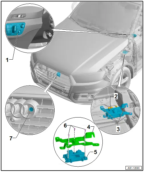
1 - Light Switch -E1- with Night Vision System Button -E680-
- Removing and installing. Refer to → Electrical Equipment; Rep. Gr.96; Controls; Component Location Overview - Instrument Panel Controls.
2 - Bracket
3 - Nut
- 3 Nm
- Quantity: 4
4 - Bracket
5 - Night Vision System Control Module -J853-
- Connector Assignment. Refer to → Wiring diagrams, Troubleshooting & Component locations.
- Removing and Installing. Refer to → Chapter "Night Vision System Control Module, Removing and Installing".
6 - Bolt
- 6 Nm
- Quantity: 4
7 - Night Vision System Camera -R212-
- Overview. Refer to → Chapter "Overview - Night Vision System Camera -R212-".
- Removing and Installing. Refer to → Chapter "Night Vision System Camera, Removing and Installing".
- Calibration. Refer to → Suspension, Wheels, Steering; Rep. Gr.44; Night Vision System; Night Vision System, Calibrating.
Overview - Night Vision System Camera -R212-
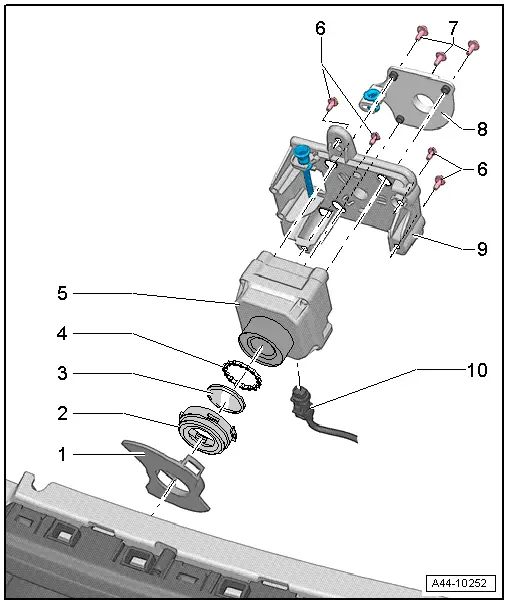
1 - Trim
2 - Cover
- With quick release
3 - Protective Window
- Removing and Installing.
 Note
Note
If the protective window is no longer water tight due to damage, then the Night Vision System Camera -R212- must be completely replaced.
4 - Seal
- Replace after every removal
5 - Night Vision System Camera -R212-
6 - Bolt
- 6 Nm
- Quantity: 4
7 - Bolt
- 5 Nm
- Quantity: 3
8 - Baseplate
9 - Baseplate
- With adjusting screw and mount for the spray nozzle
10 - 5-Pin Connector -T5C-, Black

