Audi Q7: Component Location Overview - Instrument Panel Controls
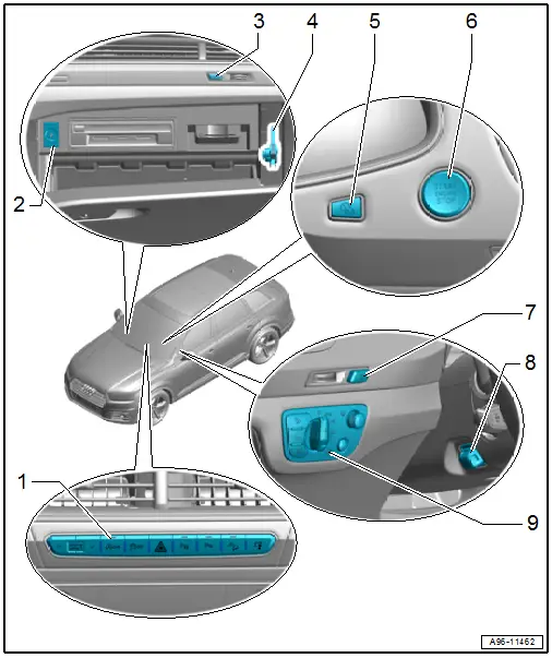
1 - Control Unit 1 for Driving and Convenience Functions -E791-
- With the following integrated components
- Emergency Flasher Button -E229-
- ASR/ESP Button -E256-
- Parking Aid Button -E266-
- Front Display Open/Close Button -E462-
- Parallel Parking Assistance Button -E581-
- Hill Descent Control Button -E618-
- Start/Stop Mode Button -E693-
- Driving Profile Selection Button -E735-
- The components cannot be replaced separately.
- If faulty replace a component of the switch module
- Removing and installing. Refer to → Chapter "Buttons in Instrument Panel, Removing and Installing, Control Unit 1 for Driving and Convenience Functions -E791-".
2 - Glove Compartment Lamp Switch -E26-
- Removing and installing. Refer to → Chapter "Glove Compartment Lamp Switch -E26-, Removing and Installing".
3 - Front Passenger Airbag Deactivation Key Switch -E224-
- Equipment level
- Removing and installing. Refer to → Body Interior; Rep. Gr.69; Front Passenger Airbag; Front Passenger Airbag Deactivation Key Switch, Removing and Installing (Not for North America).
4 - Instrument Panel Vent Button -E815-
- Equipment level
- Removing and installing. Refer to → Chapter "Instrument Panel Vent Button -E815-, Removing and Installing".
5 - Instrument Cluster Operation Button -E493-
- Removing and installing. Refer to → Chapter "Buttons in Instrument Panel, Removing and Installing, Instrument Cluster Operation Button -E493-".
6 - Access/Start Authorization Button -E408-
- Removing and installing. Refer to → Chapter "Access/Start Authorization Button -E408-, Removing and Installing".
7 - Driver Side Ionizer Button -E830-
- Equipment level
- Removing and installing. Refer to → Chapter "Driver Side Ionizer Button -E830-, Removing and Installing".
8 - Steering Column Adjustment Switch -E167-
- Removing and installing. Refer to → Chapter "Steering Column Adjustment Switch -E167-, Removing and Installing".
9 - Light Switch -E1-
- With Instrument Panel and Switch Illumination Dimmer Switch -E20-
- With Rear Fog Lamp Button -E314-, Fog Lamp Button -E315-, and Night Vision System Button -E680-
- Removing and installing. Refer to → Chapter "Light Switch -E1-, Removing and Installing".
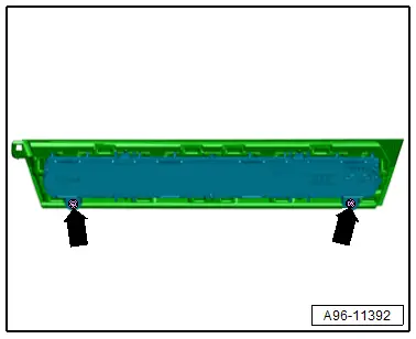
Light Switch -E1- Tightening Specification
- Tighten the screws -arrows- to 1.5 Nm.
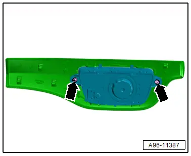
Control Unit 1 for Driving and Convenience Functions -E791- Tightening Specification
- Tighten the screws -arrows- to 1.5 Nm.
Component Location Overview - Controls in Front Doors
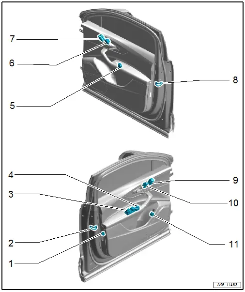
1 - Interior Monitoring and Vehicle Inclination Deactivation Button -E616-
- Removing and installing. Refer to → Chapter "Interior Monitoring and Vehicle Inclination Deactivation Button -E616-, Removing and Installing".
2 - Driver Door Contact Switch -F2-
- Integrated in the door lock.
- Cannot be replaced separately
- Replace the door locks if faulty. Refer to → Body Exterior; Rep. Gr.57; Door Components; Door Lock, Removing and Installing.
3 - Power Window Control Head in Driver Door -E512-
- With the following integrated components
- Driver Power Window Button -E710-
- Driver Side Rear Power Window Button In Driver Door -E712-
- Passenger Side Rear Power Window Button In Driver Door -E714-
- Front Passenger Power Window Button in Driver Door -E715-
- The components cannot be replaced separately.
- Replace the control head if faulty
- Removing and installing. Refer to → Chapter "Power Window Control Head in Driver Door -E512-, Removing and Installing".
4 - Mirror Adjusting Switch -E43- with Mirror Adjusting Switch -E48-
- Removing and installing. Refer to → Chapter "Mirror Adjusting Switches -E43-/-E168-, Removing and Installing".
5 - Front Passenger Power Window Button -E716-
- Removing and installing. Refer to → Chapter "Front Passenger Door Window Regulator Switch -E107-, Removing and Installing".
6 - Front Passenger Interior Locking Button -E309-
- Removing and installing. Refer to → Chapter "Driver and Front Passenger Interior Locking Switch -E150-/-E198-, Removing and Installing".
7 - Front Passenger Memory Seat Button -E340-
- Removing and installing. Refer to → Chapter "Driver and Front Passenger Seat Memory Settings Control Head -E464-/-E465-, Removing and Installing".
8 - Front Passenger Door Contact Switch -F3-
- Integrated in the door lock.
- Cannot be replaced separately
- Replace the door locks if faulty. Refer to → Body Exterior; Rep. Gr.57; Door Components; Door Lock, Removing and Installing.
9 - Driver Seat Memory Settings Control Head -E464-
- Removing and installing. Refer to → Chapter "Driver and Front Passenger Seat Memory Settings Control Head -E464-/-E465-, Removing and Installing".
10 - Driver Interior Locking Button -E308-
- Removing and installing. Refer to → Chapter "Driver and Front Passenger Interior Locking Switch -E150-/-E198-, Removing and Installing".
11 - Rear Lid Remote Release Button -E233-
- Removing and installing. Refer to → Chapter "Rear Lid Remote Release Button -E233-, Removing and Installing".
Component Location Overview - Controls in Rear Doors
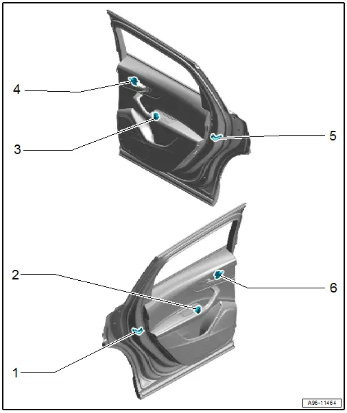
1 - Driver Side Rear Door Contact Switch -F505-
- Integrated in the door lock.
- Cannot be replaced separately
- Replace the door locks if faulty. Refer to → Body Exterior; Rep. Gr.58; Door Components; Door Lock, Removing and Installing.
2 - Driver Side Rear Power Window Button -E711-
- Removing and installing. Refer to → Chapter "Rear Window Regulator Button in Rear Door, Removing and Installing".
3 - Passenger Side Rear Power Window Button -E713-
- Removing and installing. Refer to → Chapter "Rear Window Regulator Button in Rear Door, Removing and Installing".
4 - Passenger Side Rear Interior Locking Button -E718-
- Equipment level
- Removing and installing. Refer to → Chapter "Left and Right Rear Interior Locking Switch -E273-/-E274-, Removing and Installing".
5 - Passenger Side Rear Door Contact Switch -F506-
- Integrated in the door lock.
- Cannot be replaced separately
- Replace the door locks if faulty. Refer to → Body Exterior; Rep. Gr.58; Door Components; Door Lock, Removing and Installing.
6 - Driver Side Rear Interior Locking Button -E717-
- Equipment level
- Removing and installing. Refer to → Chapter "Left and Right Rear Interior Locking Switch -E273-/-E274-, Removing and Installing".

