Audi Q7: Evaporator, Removing and Installing
Front Heater and A/C Unit Evaporator Housing, Removing and Installing
 Note
Note
- The evaporator is currently not available as a replacement evaporator for all versions. Therefore check in advance whether this evaporator is available as a replacement part or together with the replacement evaporator. Refer to the Parts Catalog. If the evaporator is supplied only together with the evaporator housing, then the evaporator housing must not be disassembled. Then the evaporator and the evaporator housing are replaced completely. Refer to → Chapter "Overview - Evaporator Housing".
- The removed evaporator contains refrigerant oil that must be returned to the refrigerant circuit (with the new evaporator). Refer to → Refrigerant R134a Servicing; Rep. Gr.87; Refrigerant Circuit Components, Replacing.
Removing
- Turn off the ignition.
- Discharge the refrigerant circuit. Refer to → Refrigerant R134a Servicing; Rep. Gr.87; Refrigerant Circuit.
- Remove the front heater and A/C unit. Refer to → Chapter "Heater and A/C Unit, Removing and Installing".
- Remove the air intake housing from the heater and A/C unit. Refer to → Chapter "Air Intake Housing from Heater and A/C Unit, Removing and Installing".
"Mix" or "High" A/C System:
- Remove the Rear Temperature Control Door Motor -V137--C- and the corresponding bracket. Refer to → Chapter "Rear Temperature Control Door Motor -V137-, Removing and Installing".
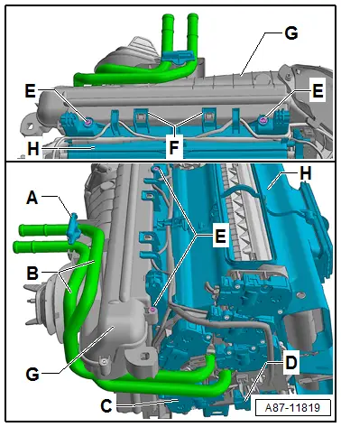
- If necessary (depending on the installation position of the screw-type clamps on the coolant pipes) remove the additional adjustment motors -D- ( Left Footwell Door Motor -V108- and Left Footwell Temperature Control Door Motor -V411-). Refer to → Chapter "Left Footwell Temperature Control Door Motor -V411-, Removing and Installing" and → Chapter "Left Footwell Door Motor -V108-, Removing and Installing".
Continuation for All
- Remove the bracket -A-.
- Remove both coolant pipes -B- from the heat exchanger (refer to → Chapter "Heater Core, Removing and Installing") and remove the coolant pipes.
- Remove the connector from the Evaporator Vent Temperature Sensor -G263-. Refer to → Chapter "Evaporator Vent Temperature Sensor -G263-, Removing and Installing".
- Remove the bolts -E-.
- Carefully release the tabs -F-.
- Disconnect the evaporator housing -G- and the air distribution box -H-.
Installing
Installation is done is reverse order, observe the following:
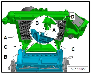
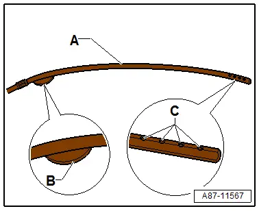
- Check the evaporator housing -A- for contamination and at the same time pay special attention to the duct for the condensation water drain -C- and the evaporator -D-.
- Check the doors in the air distribution housing -B- for damage and correct installation.
- Check the air distribution box -B- for debris or damage.
- Check the connection point between the air distribution box -B- and the evaporator housing -A- (groove / spring connection) for damage and lightly coat the connection points of the evaporator housing with silicone grease. Refer to → Chapter "Overview - Front Heater and A/C Unit".
- Engage the evaporator housing on the air distribution box and assemble with this.
- Check the heater core connection and the coolant pipes before installing for damage or debris. Refer to → Chapter "Heater Core, Removing and Installing".

 Caution
Risk of leaks at the heater core.
Crushed O-rings, coolant pipes that are tilted or have not been inserted completely may lead to leaks.
- Perform the basic setting and the output diagnostic test mode of the A/C system. Refer to Vehicle Diagnostic Tester in the "Guided Fault Finding" function.
 Note
Note
- In this vehicle, the actuators are equipped with electronics. During the basic setting, a new control motor learns its position on the heater and A/C unit and can then be activated by the Front A/C Display Control Head -E87- (currently all actuators are identical). Refer to Vehicle Diagnostic Tester in the "Guided Fault Finding" function.
- During the basic setting, the actuators are assigned and adapted corresponding to the switching sequence of the wiring. If this sequence does not conform with the specification, the actuators will adapt incorrectly and the door control will be wrong. Refer to → Chapter "Main Wiring Diagram for A/C System Actuators".
- Operate the A/C system after charging the refrigerant circuit. Refer to → Chapter "A/C System, Starting after Charging Refrigerant Circuit".
 Note
Note
Note the information regarding operating the A/C system after filling. Refer to → Refrigerant R134a Servicing; Rep. Gr.87; A/C System, General Information.
Evaporator in Front Heater and A/C Unit, Removing and Installing
 Note
Note
- The evaporator is currently not available as a replacement evaporator for all versions. Therefore check in advance whether this evaporator is available as a replacement part or together with the replacement evaporator. Refer to the Parts Catalog. If the evaporator is supplied only together with the evaporator housing, then the evaporator housing must not be disassembled. Then the evaporator and the evaporator housing are replaced completely. Refer to → Chapter "Overview - Evaporator Housing".
- The removed evaporator contains refrigerant oil that must be returned to the refrigerant circuit (with the new evaporator). Refer to → Refrigerant R134a Servicing; Rep. Gr.87; Refrigerant Circuit Components, Replacing.
Removing
- Turn off the ignition.
- Discharge the refrigerant circuit. Refer to → Refrigerant R134a Servicing; Rep. Gr.87; Refrigerant Circuit.
- Remove the front heater and A/C unit. Refer to → Chapter "Heater and A/C Unit, Removing and Installing".
- Remove the air intake housing from the heater and A/C unit. Refer to → Chapter "Air Intake Housing from Heater and A/C Unit, Removing and Installing".
- Remove the evaporator housing -A- from the air distribution box -B- from the front heater and A/C unit. Refer to → Chapter "Front Heater and A/C Unit Evaporator Housing, Removing and Installing".
- Remove the evaporator -D- from the evaporator housing -A-. Refer to → Chapter "Overview - Evaporator Housing".
Installing
Installation is done is reverse order, observe the following:
- Check the evaporator housing -A- for contamination and at the same time pay special attention to the duct for the condensation water drains -C- and the evaporator -D-.
- Install the evaporator housing -A- on the air distribution box -B- from the front heater and A/C unit. Refer to → Chapter "Front Heater and A/C Unit Evaporator Housing, Removing and Installing".
- Perform the basic setting and the output diagnostic test mode of the A/C system. Refer to Vehicle Diagnostic Tester in the "Guided Fault Finding" function.
 Note
Note
- In this vehicle, the actuators are equipped with electronics. During the basic setting, a new control motor learns its position on the heater and A/C unit and can then be activated by the Front A/C Display Control Head -E87- (currently all actuators are identical). Refer to Vehicle Diagnostic Tester in the "Guided Fault Finding" function.
- During the basic setting, the actuators are assigned and adapted corresponding to the switching sequence of the wiring. If this sequence does not conform with the specification, the actuators will adapt incorrectly and the door control will be wrong. Refer to → Chapter "Main Wiring Diagram for A/C System Actuators".
- Operate the A/C system after charging the refrigerant circuit. Refer to → Chapter "A/C System, Starting after Charging Refrigerant Circuit".
 Note
Note
Note the information regarding operating the A/C system after filling. Refer to → Refrigerant R134a Servicing; Rep. Gr.87; A/C System, General Information.
Evaporator, Cleaning
Evaporator in Front Heater and A/C Unit, Cleaning
 Note
Note
- Depending on vehicle equipment, there are different versions of the A/C system for the Audi Q7. Make sure to use the correct version and pay attention to the allocation of different components. Refer to → Chapter "A/C System Versions" and Parts Catalog.
- The evaporator in the rear heater and A/C unit (only installed on vehicles with a "High" A/C system) can currently only be clean using the Ultrasound A/C Cleaner -VAS6189B- while installed. The evaporator is installed under the center console and is only accessible after removal of various components. Refer to → Chapter "Rear Fresh Air Blower -V80-, Removing and Installing". In this vehicle, the air escaping from the rear heater and A/C unit is drawn in either by the front heater and A/C unit or under the center console depending on the setting on the Front A/C Display Control Head -E87-, the Rear A/C Display Control Head -E265- and the prevailing environmental conditions. The air coming from the front heater and A/C unit is first routed through the dust and pollen filter and the evaporator in the front heater and A/C unit. Since the dust particles in the air are filtered out here, these cannot reach the evaporator in the rear heater and A/C unit.
- To clean the evaporator in the rear heater and A/C unit with the Ultrasound A/C Cleaner -VAS6189B-, set the air distribution on the front heater and A/C unit so that the major part of the air is routed to the rear heater and A/C unit, and clean the evaporator in the same way as described for the front evaporator (in recirculation mode the air and vaporous cleaning fluid are drawn in at the front and routed to the rear heater and A/C unit). If the rear heater and A/C unit is in the recirculating air mode if necessary change the settings on the A/C system (on the Rear A/C Display Control Head -E265-) so that the air is extracted out of the front heater and A/C unit.
- In recirculation mode, the rear heater and A/C unit draws in air under the center console in the front seat area via the installed Rear Fresh Air Blower -V80-. If odors occur in the rear heater and A/C unit, check the center console and the area under the front seats for moisture and contamination. Check the condensation water drains in the rear A/C unit for blockage and the heat exchanger installed in the rear heater and A/C unit for leaks. Refer to → Chapter "Condensation Water Drain Hose, Checking" and → Chapter "Component Location Overview - Rear Adjustment Motor".
Evaporator in Front (and Rear) Heater and A/C Unit, Cleaning with the Ultrasound A/C Cleaner
Special tools and workshop equipment required
- Ultrasound A/C Cleaner (for example the Ultrasound A/C Cleaner -VAS6189B-). Refer to the Tool Catalog for the cleaning device currently available.
- Ultrasound A/C Cleaner - Airco-Clean Fluid -VAS6189/1-
Preparation
- Check by switching from fresh air to recirculating air mode to see if the noise is actually located in the evaporator of the front heater and A/C unit (in the rear heater and A/C unit).
 Note
Note
The odor can only be removed by cleaning with the Ultrasound A/C Cleaner (for example the Ultrasound A/C Cleaner -VAS6189B-) if it originates in the evaporator.
- Check the plenum chamber and the water drain valves for dirt and debris and clean if necessary. Refer to → Chapter "Plenum Chamber Water Drain, Removing and Installing".
- Remove the dust and pollen filter and check for odors and dirt. Refer to → Chapter "Dust and Pollen Filter, Removing and Installing".
 Note
Note
On this vehicle, dust and pollen filter is installed before the Fresh Air Blower -V2-, therefore it must not be removed for cleaning the evaporator.
- Clean the installation slot of the front heater and A/C unit dust and pollen filter (remove leaves, dust and other contaminants). Refer to → Chapter "Dust and Pollen Filter, Removing and Installing".
- Reseal the opening on the heater and A/C unit through which dust and pollen filter was removed.
- Start the engine.
- Adjust the recirculating air mode on the Front A/C Display Control Head -E87- (-A or B-) (the indicator lamp in the "recirculating air mode" turns on) and the switch off the A/C compressor (the indicator lamp in the A/C or A/C MAX button illuminates.
- Open the instrument panel vents and the vents in the rear center console.
- Adjust the smallest possible temperature on the Front A/C Display Control Head -E87- (-A or B-) (for the driver and front passenger side) ("cold" temperature setting).
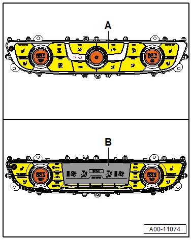
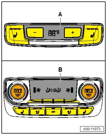
- If equipped adjust the Rear A/C Display Control Head -E265- (-A or B-) also to the lowest possible temperature, "cold" temperature setting on a vehicle with a "High" A/C system, with a Rear A/C Display Control Head -E265- version -B- for both sides).
- Closes the windows and sliding sunroof.
- Adjust the lowest fresh air blower setting on the Front A/C Display Control Head -E87- (and if equipped and possible also the Rear A/C Display Control Head -E265-) and select the airflow direction of the air on the "instrument panel vent" (the rear center console vent).
- On the Front A/C Display Control Head -E87-, select the air flow direction to the "instrument panel vents".
- If equipped and possible select on the Rear A/C Display Control Head -E265- the airflow direction of the air to the rear center console vent (only possible on vehicles with a "High" A/C system).
Cleaning
- Shake the bottle of Ultrasound A/C Cleaner - Airco-Clean Fluid -VAS6189/1- and pour the contents into the Ultrasound A/C Cleaner (for example the Ultrasound A/C Cleaner -VAS6189B-) (when doing this, be sure to read the operation manual which comes with the Ultrasound A/C Cleaner.
- Place the Ultrasound A/C Cleaner (for example the Ultrasound A/C Cleaner -VAS6189B-) in the front passenger footwell.
- Start the Ultrasound A/C Cleaner (for example the Ultrasound A/C Cleaner -VAS6189B-) according to operating instructions and route the outlet hose belonging to it so that vapor escaping via the front heater and A/C unit recirculation opening (in the front passenger footwell behind the glove compartment in the area of the right wheel housing) is drawn in by the Fresh Air Blower -V2-.
 Note
Note
Via the air ducts between the front heater and A/C unit and the air distribution box/rear heater and A/C unit, part of the cleaning fluid is also drawn in by the Rear Fresh Air Blower -V80- and routed through the components in the air distribution box/rear heater and A/C unit.
- Close the vehicle doors.
 Note
Note
The cleaning process takes about 15 to 20 minutes. It is complete when vapor no longer comes out of outlet hose.
Final Procedures
- Turn off the Ultrasound A/C Cleaner (for example the Ultrasound A/C Cleaner -VAS6189B-).
- Open the vehicle doors and air out the passenger compartment for at least 10 minutes.
- Remove the Ultrasound A/C Cleaner (for example the Ultrasound A/C Cleaner -VAS6189B-) from vehicle and clean it according to operating instructions.
- Turn off the ignition.
- Install the dust and pollen filter. Refer to → Chapter "Dust and Pollen Filter, Removing and Installing".
Evaporator on Front Heater and A/C Unit, Cleaning, with Suction Feed Spray Gun -VAG1538- and a Spray Lance
 Note
Note
- Depending on vehicle equipment, there are different versions of the A/C system for the Audi Q7. Make sure to use the correct version and pay attention to the allocation of different components. Refer to → Chapter "A/C System Versions" and Parts Catalog.
- The evaporator in the rear heater and A/C unit (only installed on vehicles with a "High" A/C system) can currently only be clean using the Ultrasound A/C Cleaner (for example the Ultrasound A/C Cleaner -VAS6189B-) while installed. Refer to → Chapter "Evaporator in Front (and Rear) Heater and A/C Unit, Cleaning with the Ultrasound A/C Cleaner". The evaporator is installed under the center console and is only accessible after removal of various components. Refer to → Chapter "Rear Fresh Air Blower -V80-, Removing and Installing". In this vehicle, the air escaping from the rear heater and A/C unit is drawn in either by the front heater and A/C unit or under the center console depending on the setting on the Front A/C Display Control Head -E87-, the Rear A/C Display Control Head -E265- and the prevailing environmental conditions. The air coming from the front heater and A/C unit is first routed through the dust and pollen filter and the evaporator in the front heater and A/C unit. Since the dust particles in the air are filtered out here, these cannot reach the evaporator in the rear heater and A/C unit.
Special tools and workshop equipment required
- Suction Feed Spray Gun -VAG1538-. For suction feed spray guns that can be delivered currently, refer to the Parts Catalog (Tools; Workshop Equipment and Tools; A/C and Heating).
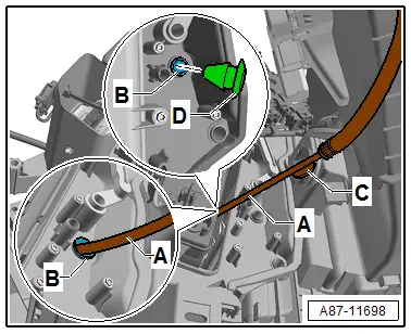
- Suction Feed Spray Gun - Probe for Evaporator (Straight) -VAG1538/5- (short version approximately 500 mm (19.6 in.), bent to specification for this vehicle) -A- or Suction Feed Spray Gun - Probe for Evaporator Cleaning, Curved -VAG1538/6- (medium version approximately 600 mm (23.6 in.) pre-bent) -A-. Currently deliverable sensors. Refer to the Parts Catalog Tools; Special Tools and Equipment: A/C and Heating).
- Commercially available angle drill and a 9 mm long drill bit (on necessity when the evaporator was not cleaned previously)
- Cleaning Solution for A/C System Evaporator "D 600 100 A2" (for cleaning fluids that can be delivered currently, refer to the Parts Catalog)
- Plugs 8D0 819 598. Refer to the Parts Catalog.
- Commercially Available Vacuum Cleaner
 WARNING
Possible contamination of the heater and A/C unit by other substances
Only use a suction feed spray gun and a spray lance that were not already used with other fluids.
 Note
Note
- The vacuum cleaner is only necessary if there is dirt in the plenum chamber or in the heater and A/C unit air intake shroud, or if dirt has gotten into the evaporator housing through the dust and pollen filter.
- It is recommended to have several short and long spray lances, since they are used either in their straight form, or must be bent to different degrees for various vehicles (or they are already bent). Repeatedly changing the form of the spray lance will damage it and is therefore not advisable.
The recommended bend radius of the Suction Feed Spray Gun - Probe for Evaporator (Straight) -VAG1538/5- (short) or Suction Feed Spray Gun - Probe for Evaporator Cleaning, Curved -VAG1538/6- (middle length) -A- for this vehicle is shown.
 Note
Note
The guide washer -B- is attached opposite of the spray lance holes -C-. This also allows the spray direction to be recognized when the spray lance is inserted.
Preliminary Work
- Turn on the ignition.
- Open all instrument panel vents.
- Switch the A/C system on.
- Check by switching from fresh air to recirculating air mode to see whether the odor is actually originating from the front heater and A/C unit evaporator. Refer to → Chapter "Information on Odors in Vehicles with A/C System".
 Note
Note
- The cause or the location of the odor must be determined before cleaning the evaporator.
- Even if the odor is not caused by the evaporator (for example, the dust and pollen filter is dirty), it is advisable to clean the evaporator after eliminating the cause (the evaporator absorbs odors via the air flowing by).
- Set the A/C system to recirculating air mode.
- Switch off the ignition (and with it the A/C system and Fresh Air Blower -V2-).
- Remove the glove compartment. Refer to → Body Interior; Rep. Gr.68; Storage Compartments and Covers; Glove Compartment, Removing and Installing.
- Remove and check the dust and pollen filter. Replace it if necessary after cleaning the evaporator. Refer to → Chapter "Dust and Pollen Filter, Removing and Installing".
 Note
Note
Replacing a dirty dust and pollen filter is recommended after each cleaning.
- When removing the dust and pollen filter check the area of the dust and pollen filter (to the air intake shroud doe the air in the fresh and recirculating air mode) and clean if necessary. Refer to → Chapter "Dust and Pollen Filter, Removing and Installing".
- Check the plenum chamber and the plenum chamber water drain and clean them if necessary. Refer to → Chapter "Plenum Chamber Water Drain, Removing and Installing".
 Note
Note
The water drains in the plenum chamber must be checked according to the repair manual before starting to clean. Clean them if necessary. Refer to → Chapter "Plenum Chamber Water Drain, Removing and Installing".
- Place a drip tray under the vehicle to collect the cleaning fluid that is draining out via the condensation water drain (for the outlet opening layout for the condensation water drain. Refer to → Chapter "Condensation Water Drain, Removing and Installing").
- Cover the carpet in the front passenger footwell with a liquid-tight cover and absorbent paper.

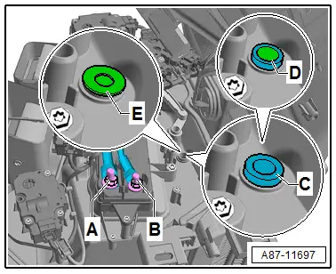
- On vehicles with Auxiliary Heater Control Module -J604- cover the connections -A and B-.
 Caution
On a vehicle with an Auxiliary Heater Control Module -J604-, there is a risk of short circuit my touching the connections -A and B- at the same time with spray lance, the drill bit or the drill.
Cover the connections -A and B- so that they do not come in contact with electrically conductive tools (spray lance, the drill bit or the drill).
 Note
Note
On the connection -A- the ground is present and on the connection -B- the positive (terminal 30).

- On a vehicle with a evaporator which was already cleaned once with a spray lance, remove the plugs -E-.
On a vehicle with an evaporator which has not been cleaned with a spray lance.
 Caution
The heater and A/C unit or the doors in the heater and A/C unit could be damaged.
- Route the connecting lines on the heater and A/C unit so that they do not come in contact with the turning parts of the drill or the drill bit.
- Only drill carefully and with low speed.
- Do not let the drill enter deeper than maximum 10 mm in the heater and A/C unit.
- Using a commercially available angle drill and a short drill bit (9 mm diameter) carefully drill a hole -D- in the evaporator to be cleaned installed pin -C- on the front heater and A/C unit.
- Remove any burrs from the hole -D-.
Evaporator, Cleaning
 WARNING
The cleaning solution is combustible. Vapors may form an explosive mixture with the air.
- Keep any ignition sources away and do not smoke.
- Only work with the cleaning solution in well-ventilated areas.
Cleaning solution may pose a health risk.
Protect eyes by wearing protective eyewear.
- Use safety equipment, such as protective eyewear and gloves.
- Keep an eye bath on hand.
- If the cleaning solution has come in contact with the eyes, flush them thoroughly with cool or lukewarm water for 15 minutes.
- Then apply eye drops and consult a doctor immediately even if no pain is felt.
- Inform the doctor which cleaning solution has gotten into the eyes.
Protect hands by wearing rubber gloves.
- Use safety equipment, such as protective eyewear and gloves.
- If liquid cleaning solution has come in contact with the hands or skin, clean them with soap and water and rinse thoroughly.
Do not breathe in the cleaning fluid vapors and do not ingest any cleaning fluid.
- Only work with the cleaning solution in well-ventilated areas.
- If any liquid cleaning solution was ingested, do not induce vomiting. Consult a doctor immediately.
- Inform the doctor which cleaning solution was ingested.
 Caution
Risk of damaging the vehicle by the cleaning fluid
- Avoid getting any fluid on the electronic components.
- Do not spray the cleaning fluid into the air ducts leading to or in the vehicle interior.
- If vehicle interior components have come in contact with the cleaning fluid, they must be thoroughly cleaned.
- The ignition (along with the A/C system) is switched off.
- The preliminary work was performed and the specified components are removed.
- Fill the suction feed spray gun with the attached spray lance with one liter of cleaning solution for the A/C system evaporator.
- Set a pressure of approximately 7.5 bar (108.77 psi) on the compressed air supply for the suction feed spray gun (minimum pressure: 5 bar (72.5 psi)/maximum pressure: 10 bar (145.03 psi) ).
 Note
Note
This compressed air supply pressure results in a working pressure of 3.5 to 4.5 bar (50.76 to 65.27 psi) at the spray lance.
- Connect the Suction Feed Spray Gun -VAS1538- to the compressed air supply.
- Guide the spray lance -A- via the opening -B- in the heater and A/C unit (in the evaporator housing) spray direction toward the evaporator.
 Note
Note
The guide washer -C- for the spray lance -A- secures the spray direction.
 Caution
No cleaning fluid must flow into the vehicle interior from the heater and A/C unit evaporator housing when cleaning.
- Cover the area under the spray lance in the evaporator housing with absorbent paper.
- After spraying approximately 0.1 to 0.2 liters of cleaning fluid, check that the fluid is actually draining into the drip tray under the vehicle via the condensation water drain. The condensation water drain must be cleaned before continuing the cleaning procedure if the fluid is only dripping out. Refer to → Chapter "Condensation Water Drain, Removing and Installing".
- Clean and flush the evaporator and the surrounding housing with cleaning solution by operating the metering lever on the suction feed spray gun and moving the spray lance -A- back and forth.
 Note
Note
- The contaminate-heavy cleaning fluid flows out via the condensation water drain.
- The drainage of the cleaning fluid via the condensation water drain must be monitored during the cleaning procedure.
- Spray the entire contents of the suction feed spray gun for cleaning the evaporator.
- Remove the drip tray and dispose of the collected cleaning solution.
 Note
Note
Used cleaning solution can be disposed of, for example, via the wastewater disposal (observe the local governmental regulations). Refer to Audi, HSO Environment (or Volkswagen, Handbooks, Service Handbook; Protecting the Environment; Emissions Protection).
Allow the cleaning solution to work for at least 30 minutes.
 Note
Note
The removed components can be reinstalled at this time.
- Insert the plugs -D- in the hole -B- and check for secure fit.
- Reinstall all of the removed components.
- Open all of the doors or windows.
- Open all of the air vents on the instrument panel and in the vehicle.
- Switch on the ignition.
- Adjust the airflow direction of the air to all vents on the Front A/C Display Control Head -E87-.
- Set the maximum speed for the Fresh Air Blower -V2- on the Front A/C Display Control Head -E87-.
- Then start the engine and turn on the A/C system (the A/C compressor) (the indicator lamp in the A/C or A/C Max button turns on).
- If equipped adjust the airflow direction of the air to all vents on the Rear A/C Display Control Head -E265- version -B- (installed on vehicles with a "High" A/C system) and select the maximum speed for the Rear Fresh Air Blower -V80-.
- Allow the A/C system to run at this setting for approximately 10 minutes (the A/C compressor is switched on). At the same time, switch the selected vent temperature back and forth between cold and warm several times on the Front A/C Display Control Head -E87-.


